Figure 2, 1/07 candéo, Led operations manual – Gotham CANDÉO LED User Manual
Page 2
Part No. CJ520348
©2007 Gotham
1/07
CANDÉO
®
LED OPERATIONS MANUAL
ACCESSING THE LED DRIVER AFTER INSTALLATION FOR PROGRAMMING AND TROUBLE SHOOTING
(NON ACCESSIBLE CEILING) - BEFORE PROCEEDING, TURN OFF POWER.
If you plan to change the programming of the LED driver often, it is recommended that you purchase
an external control.
If you wish to change the programming of multiple LED drivers that are networked together and are
not controlled by an external control, identify the first (master) driver in the network and make
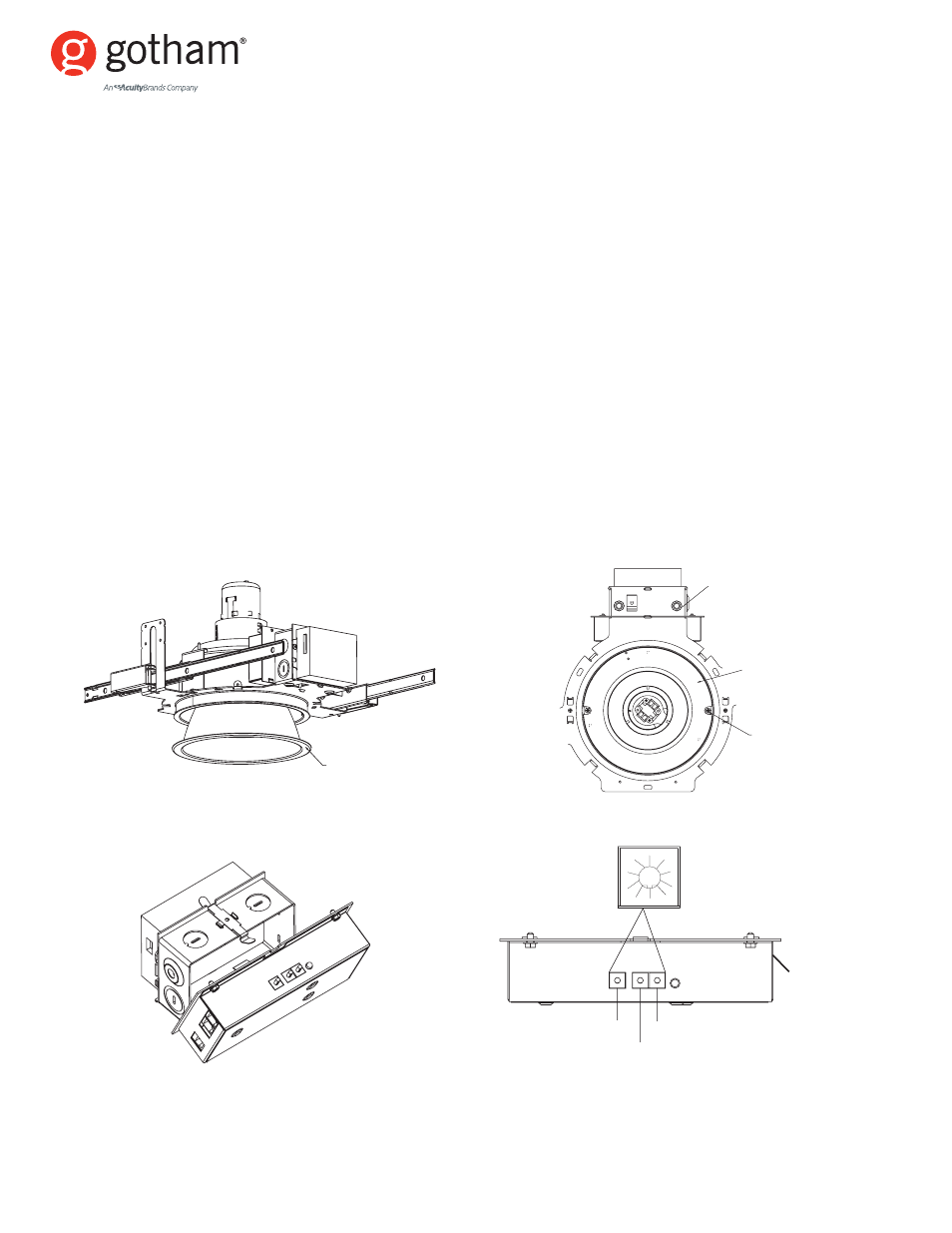
changes to it alone. In order to access the LED driver to make programming changes after the
product has been installed, you will need to remove the trim. Grip the edge of the cone flange and
pull down, releasing it from the outer reflector and exposing the LED ring (see Figure 2). The outer
reflector is held in the housing with two screws located in the slots of the LED ring (see Figure 3).
Slightly loosen the screws (do not remove), disengaging them from the keyhole slots (see Figure 3)
and twist the outer reflector counter clockwise to free it from the housing. Unplug the phone line
connecting the trim to the LED driver. Leave the compact fluorescent socket cup attached to the top
of the outer reflector and allow it to hang below the ceiling plane. You will now be able to see the
programming label on the front of the driver (see Figure 4). The LED driver is attached to the
housing’s junction box with a steel spring clip. Release the driver by raising the clip (see Figure 4).
Lay the driver label side down so that the dials are visible (see Figure 5), and using the programming
guide (see manual programming instructions on page 3), program new settings. Replace driver and
trim in reverse order and restore power.
Figure 3
Figure 4
Figure 5
LED
DRIVER
2
COLOR SWITCH
SWITCH B
SWITCH A
0
1
2
3
4
5
6
7
8
9
COLOR SWITCH SWITCH B
SWITCH A
LED DRIVER
LED RING
SCREW IN
KEYHOLE SLOT
PULL DOWN ON FLANGE
TO REMOVE TRIM
Figure 2