Gotham Candéo LED (PDLFV) Housing User Manual
Candéo, Save these instructions, Pdlfv) housing
Part No. CJ520744
©
2006 Gotham 10/06
Figure 3
Figure 4
Figure 1
Figure 2
INSTALLATION INSTRUCTIONS
Candéo
®
LED
(PDLFV) Housing
Upon receipt, thoroughly inspect for
any freight damage which should be
brought to the attention of the delivery
carrier. Compare the catalog descrip-
tion listed on the packing slip with the
label on the carton to ensure you have
received the correct merchandise.
IMPORTANT SAFETY INFORMATION
For Your Protection, Read Carefully
WARNING: Risk of fire. Do not install
insulation within 3 inches of fixture sides
or wiring compartment, nor above the
fixture in such a manner as to entrap
heat.
1. Electric current can cause painful
shock or serious injury unless handled
properly. For your safety, always
remember the following:
•
Turn off the power supply.
•
Ground the fixture to avoid poten-
tial electrical shocks.
•
Do not handle an energized fixture
or energize any fixture with wet
hands, when standing on a wet or
damp surface, or in water.
2. Specific safety information concerning
lamps:
•
Match wattage of fixture and lamp
exactly.
•
Do not remove or insert lamp when
power is on.
•
Do not scratch glass or subject lamp
to undue pressure as either may
cause lamp breakage.
•
Protect operating lamp from sources
of moisture.
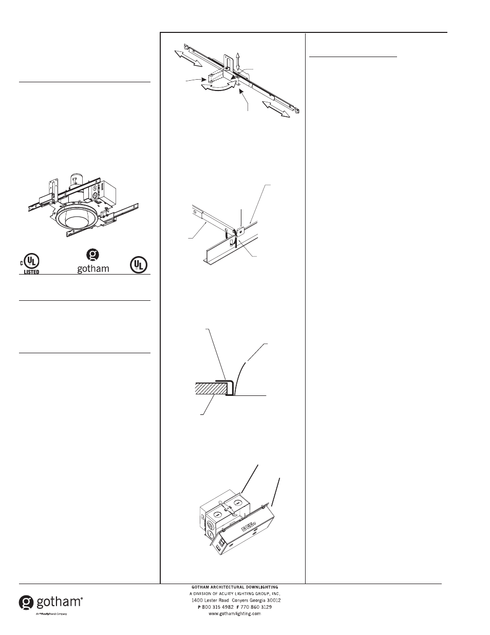
NEW INSTALLATION FOR PDLFV
Lay-in panel T-bar ceiling:
1. Cut an opening in the ceiling. This opening
must be slightly larger than the outside
diameter of the mounting frame.
2. Position mounting frame through opening
in ceiling. Release clamping latch arms and
adjust channel bars to the correct spacing
between T-bar as shown in Figure 1. Secure
channel bars to T-bar by means of wire ties,
screws, or by bending ends onto T-bar as
shown in Figure 2.
3 Once mounting frame has been secured in
structure, adjust the mounting frame vertically
to align the bottom edge to either flush or
slighty above (1/8” max) the ceiling line as
shown in Figure 3. Secure mounting frame
into position by closing the clamping latch
arms.
4. If additional security is required, a No.8 sheet
metal screw, wire tie or wire (not supplied)
may be used to tie the latch arm to the mount-
ing frame as shown in Figure 1.
5. Remove knockouts on junction box to feed
power supply to fixture as shown in Figure 4.
Supply wire must meet applicable electrical
codes and be rated for a minimum of 75
o
C.
Junction box is thru-wire rated for (8) No.12
AWG conductors (4 in - 4 out).
6. Drop socket cup and telephone cord through
mounting frame aperture.
7. Complete necessary splices. Snap the LED
driver assembly onto the junction box as
shown in Figure 4.
IMPORTANT: See Figure 6 for LED Driver and
compact fluorescent ballast wiring schematics.
Clamping
Latch Arms
Open
Closed
Bent Tab
T-Bar
Wire Tie
Channel
Bar
Mounting
Frame
Reflector
Ceiling
Junction
Box
SAVE THESE INSTRUCTIONS
LED
Driver