Installation, cont’d, Receiver connections, Power connection – Extron Electronics TPS150 User Guide User Manual
Page 18: Utp link input connection
Installation, cont’d
TPS150 Switching and Transmission System • Installation
2-6
8
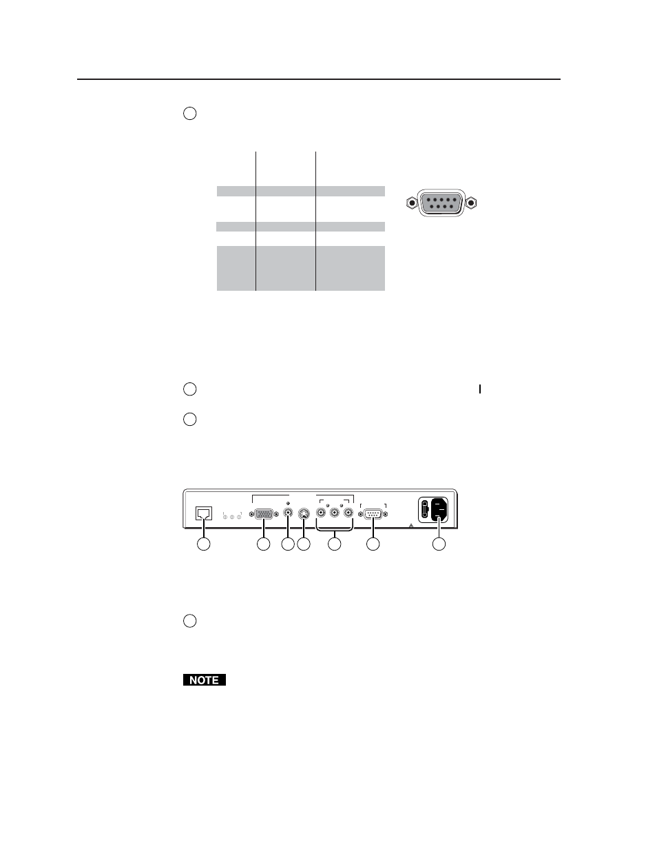
RS-232 port —
Connect a host device, such as a computer or touch panel
control, to the TPT150 transmitter via this 9-pin D connector and a null
modem serial port cable for serial RS-232 control (figure 2-6).
Connected
RS-232
device pin
Function
TPS150
pin
1
2
3
4
5
6
7
8
9
—
RX
TX
—
Gnd
—
—
—
—
Not used
Receive data
Transmit data
Not used
Signal ground
Not used
Not used
Not used
Not used
5
1
9
6
Female
Figure 2-6 — Remote port pin assignments for the TPT150 and TPR150
See chapter 4, “Serial Communications”, for definitions of the ASCII
commands and instructions to install and use the control software.
Power connection
9
AC power switch —
Toggle the AC power switch to the on ( ) position to turn
on the transmitter.
10
AC power connector —
Plug a standard IEC power cord into this connector
to connect the transmitter to a 100 to 240VAC, 50 Hz to 60 Hz power source.
Receiver connections
All receiver connectors are on the rear panel (figure 2-7).
F U S E : 1 . 6 A ; 2 5 0 V; T I M E D E L AY
9 0 - 2 6 0 VAC ; 0 . 2 5 A ; 4 7 - 6 3 H z
U T P L I N K
S K E W
R G B / VG A
C O M P O S I T E
V I D E O O U T P U T
S - V I D E O
C O M P O N E N T
R S - 2 3 2 P O RT
R - Y
B - Y
Y
R E D B L U E G R N
A D J
USE ONL
Y
WITH 250V FUSE
15
12
13 14
16
11
17
Figure 2-7 — TPR150 receiver rear panel connectors
UTP Link Input connection
11
Input UTP Link connector —
Connect the free end of the TP cable from the
transmitter to this RJ-45 female connector on the receiver.
See “TP Cable Termination”, on page 2-8, to properly wire the RJ-45
connector.
The TPS150 works with either shielded or unshielded cables. However, to
comply with FCC rules, shielded (STP or FTP) cables must be used.