Aux/mix input connection, Control connection, 7 pvs 204sa switcher • installation – Extron Electronics PVS 204SA User Guide User Manual
Page 19: Caution
2-7
PVS 204SA Switcher • Installation
ã
Stereo and Dual Mono selection
— To select stereo or dual mono audio
output, set the switch to the desired position. Dual mono sums left and
right audio signals together and outputs the same signals on both audio
output channels. Default setting is mono.
N
For best results when speech is the primary audio, set this switch for dual mono
with the high pass filter set to on. If music is involved, set the switch to stereo
with the high pass filter set to off.
Aux/Mix input connection
g
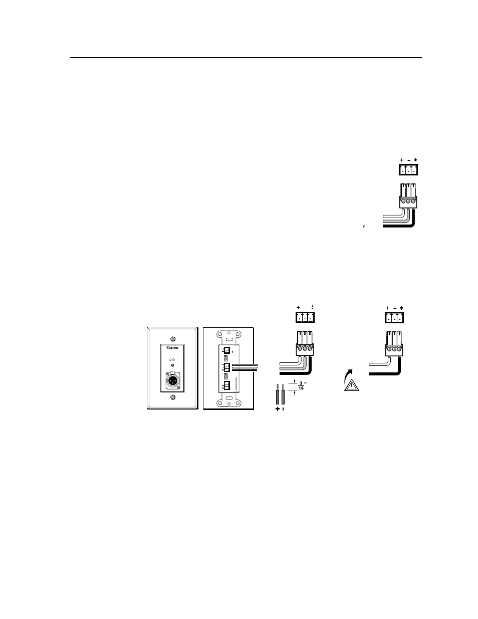
Aux/Mix audio input — To mix an auxiliary, mono, line-
level audio signal (from a wireless microphone receiver,
for example) with the selected input’s audio, connect the
cable from the mono source to this 3-pole captive screw
connector. The signal can be balanced or unbalanced.
Wire the supplied blue 3-pole male captive screw connector
as shown at right.
N
This audio input signal is present regardless of the selected input on the
switcher. The audio level is not affected by the program volume.
For wired microphones, connect an Extron MLP 101 microphone-to-
line preamplifier to the Aux/Mix port on the PVS 204SA, to convert the
microphone output to line level. Follow the installation instructions in the
user manual supplied with the MLP 101 to connect the microphone. See
figure 2-8 to wire the MLP to the switcher.
Captive Screw
Connector Wire Stripping
(5 mm) MAX.
Balanced
Input
Unbalanced
Input
CAUTION
For unbalanced audio, connect the
sleeve(s) to the ground.
DO NOT
connect the sleeve(s) to the
negative (-) contact.
PO
W
E
R
12V
0.2A MAX
LINE
OUTPUT
REM
O
TE
10V
V
OL/MUTE
ON
OFF
ON
OFF
PHANT
OM
LO
W CUT
MIC
TO LINE
PREAMPLIFIER
MLP 101 D
MIC IN
ACTIVE
MUTE
MLP 101 D front and rear panels
Tip
Sleeve
Ring
AUX/MIX IN
NO Ground Here
Tip
Sleeve
AUX/MIX IN
To
PVS
To
PVS
Figure 2-8 — Wiring an MLP 101 D to the PVS 204SA Aux/Mix connector
AUX/MIX IN
+ Positive
– Negative
Ground