Rear panel – Extron Electronics LANCIAxi User Guide User Manual
Page 17
Extron • SENTOSA
xi
LQ & LANCIA
xi
LD • User’s Manual
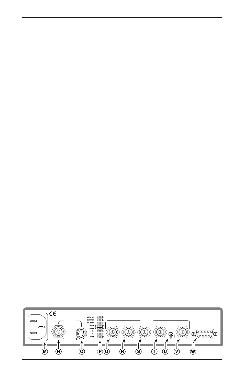
Rear Panel
The following descriptions are keyed* to the rear panel drawing
below. Sentosa
xi
panel is pictured but also applies to Lancia
xi
.
M
AC Power connector
Standard IEC AC power connector (100 - 240 VAC 50/60 Hz)
N
1 = Input connector #1
BNC connector for composite input video.
O
2 = Input connector #2
4 Pin mini-DIN connector for S-Video input.
P
Switch Module
8 DIP switches described on pages 2-3 & 2-4.
Q
R = Red output BNC connector
For Red video output
R
G = Green output BNC connector
For Green video output (plus HV sync if H/HV/SOG switch = SOG)
S
B = Blue output BNC connector
For Blue video output
T
H/HV sync output BNC connector
The output from this connector is dependent on the setting of the
three position switch described in “U” below.
U
H/HV/SOG 3-position switch
The position of this switch determines horizontal and vertical sync
output location.
Switch = top (H) position, H sync on H/HV BNC, V sync on V BNC
Switch = center (HV) position, Composite HV sync on H/HV BNC
Switch = bottom (SOG) position, Sync on Green BNC
V
V = Vertical Sync Output BNC Connector
The output from this connector is dependent on the setting of the
three position switch described in “U” above.
W
RS-232/Contact REMOTE 9 pin connector
When connected to a serial port on a Host computer/device,
remote (manual or program) control of the Sentosa
xi
or Lancia
xi
is
possible. A third party remote contact closure device may be
connected to this connector (see Page 3-5, “Remote Contact
Closure Operation”, for details).
* –
Letters next to the descriptions above are keyed to the circled
letters in the drawing below.
H
SOG
H/V
R
G
B
H/HV
V
OUTPUT
RS-232
INPUTS
REMOTE
100-240VAC 50/60Hz
100 mA MAX
Page 2-6
Installation and Operation