Power supply wiring and grounding – Extron Electronics MTP T 15HD A User Guide User Manual
Page 17
MTP T 15HD A Architectural Series • Installation
11
d
Frequency Select switch — The Frequency select DIP switch sets the vertical
frequency of the factory-installed EDID. 50 Hz or 60 Hz can be selected.
e
EDID Select rotary switch — This 16 position rotary switch is used to select which
factory-installed EDID information will be used. Position 0 is not used. Positions 1
through F correspond to the EDID information in the table in figure 15 on page
.
f
Power connector — Connect the cables from the included external 12 VDC power
supply to the rear panel 3.5 mm, 2-pole captive screw connector (see figures 12 and 13
below and on the next page for wiring and grounding instructions).
To verify the polarity before connection, plug in the power supply with no load and
check the output with a voltmeter.
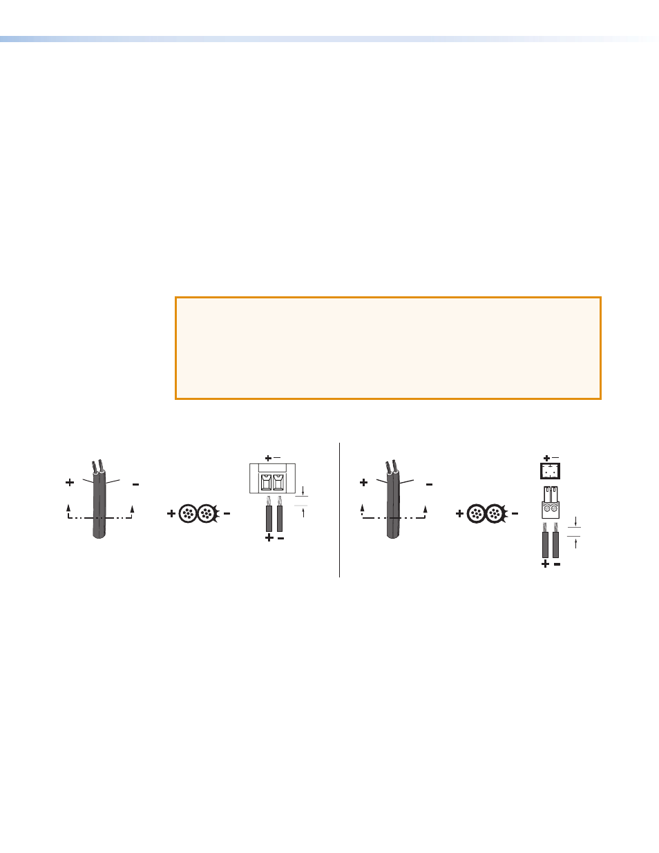
Power Supply Wiring and Grounding
Figure 12 shows how to wire the power connector. Figure 13 shows how to ground the unit
through the power connector.
ATTENTION: Potential damage to property.
•
Power supply voltage polarity is critical. Incorrect voltage polarity can damage the
power supply and the transmitter or receiver. Identify the power cord negative lead
by the ridges on the side of the cord.
•
The length of the exposed (stripped) copper wires is important. The ideal length is
3/16 inches (5 mm). Longer bare wires can short together. Shorter wires are not as
secure in the connector and could be pulled out.
To verify the polarity before connection, plug in the power supply with no load and check the
output with a voltmeter.
Power Supply
Output Cord
Captive Screw
Connector
3/16” (5 mm)
MAX
SECTION A–A
Ridges
Smooth
A
A
Power Supply
Output Cord
Captive
Screw
Connector
SECTION A–A
Ridges
Smooth
A
A
3/16” (5 mm)
MAX
Figure 12.
Power Connector Wiring for the MTP T 15HD WM and AAP (Left), and
the MTP T 15HD A D (Right)
Extron twisted pair products can be adversely affected by electrostatic discharge (ESD) if
they are not grounded correctly. To prevent malfunctions or product damage, an installer
can correctly ground an Extron twisted pair product by following the diagram in figure 13 on
the next page.
Ground the power port by inserting one end of the grounding wire to the negative or ground
pin on the power input connector.