Rear panel features – Extron Electronics MTP T 15HD A User Guide User Manual
Page 16
MTP T 15HD A Architectural Series • Installation
10
Rear Panel Features
With the exceptions of
d
,
e
, and
f
on the MTP T 15HD A D, as noted in the figures and
descriptions, the rear panel features are the same on all the MTP T 15HD A architectural
models.
50
ON
OFF
60
Hz
PRE-
PEAK
EDID
SELECT
3
1
1
2
3
4
5
6
2
6
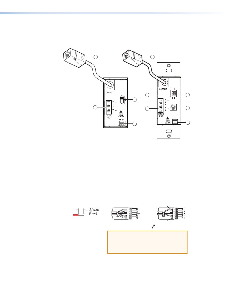
Figure 10.
MTP T 15HD WM and AAP (Left) and MTP T 15HD A D (Right)
Rear Panel Features
a
Output connector — Connect one end of a twisted pair cable to this RJ-45 female
connector on the transmitter. Connect the opposite end of the cable to the RJ-45
connector of the receiver (see
Twisted Pair Cable Termination
on page 13 to wire the
RJ-45 connectors).
b
Pre-Peak switch — The Pre-Peak DIP switch boosts the video signal output to correct
for long cable runs (see the table on page
for suggested switch settings based on the
transmitted video format and transmission distance).
c
Stereo Audio output connector — Insert bare wires into this direct insertion 3.5 mm,
5-pole captive screw audio connector for stereo audio outputs. Wire the connector as
shown in figure 11.
Do not tin the wires!
Balanced Audio Output
Tip
Ring
Tip
Ring
Sleeves
Unbalanced Audio Output
Tip
No Ground Here
No Ground Here
Tip
Sleeves
LR
LR
ATTENTION: Potential damage to property.
For unbalanced audio, connect the sleeves
to the ground contact.
DO NOT
connect the sleeves to the
negative (-) contacts.
Figure 11.
Captive Screw Audio Connector Wiring