Connections and settings, Front panel features – Extron Electronics MTP T 15HD A User Guide User Manual
Page 15
MTP T 15HD A Architectural Series • Installation
9
Connections and Settings
ATTENTION: Potential damage to property.
Do not connect these devices to a computer data or telecommunications network.
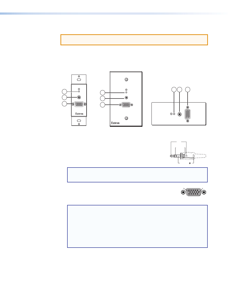
Front Panel Features
The front panel features are the same on all the MTP T 15HD A architectural models, as
shown in figure 9.
AUDIO IN
MTP T 15HD A
COMPUTER IN
MTP T 15HD A D
MTP T 15HD A WM
AUDIO IN
MTP T 15HD A
COMPUTER
IN
MTP T 15HD A AAP
COMPUTER IN
AUDIO IN
1
3
2
1 2
3
1
3
2
Figure 9.
Architectural Series Front Panel Features
a
Power LED — Indicates power is applied to the MTP.
b
Audio input connector — Connect a 3.5 mm stereo audio
plug into this jack for unbalanced audio input. Wire the plug as
shown in the figure to the right.
NOTE: The figure above shows a typical audio connector, which consists of the tip,
ring, and sleeve. The tip, ring, and sleeve wires are also shown on the captive
screw audio connector diagram (see figure 11 on page
c
Video input connector — Connect a computer video source to this
15-pin HD connector for high resolution video input.
NOTES:
•
Input only sync signals (no video signals) on the sync pins (13 and 14).
•
For component video, use the R (R-Y) and R return pins (pins 1 and 6),
G (Y) and G return pins (pins 2 and 7), and B (B-Y) and B return pins
(pins 3 and 8).
•
For S-video, use the R, R return (C-chroma), G, and G return (Y-luma) pins.
•
For composite video, use the G pin and the associated return pin. For
additional genlocked video signals, use the R, B, and associated return pins.
Sleeve ( )
Ring
Right (-)
Tip
Left (+)
5
1
15
11
6
10
Female