Command/resp onse table for sis commands, Command/response table for sis commands, Input – Extron Electronics MTP SW6 User Guide User Manual
Page 27: Selection, Sis commands for details, Available as an sis command. see the, Auto level and peaking, Adjustment, Sis command, Section and the
Command
ASCII Command
(host to unit)
Response
(unit to host)
Additional description
Input selection
NOTE:
The switcher supports 1-, 2-, or 3-digit numeric entries (1!, 02&, or 003%). The switcher reports all selections with 1-digit
numbers.
NOTE:
The & select and % select commands for video can be used interchangeably.
Select input
X!
video and
audio to output
X!
!
All
X!]
Select input
X!
video and audio to be the output.
Example:
1!
All1
]
Select input 1 video and audio.
Select input
X!
video
only to output
X!
&
Vid
X!]
Select
X!
video (audio is broken away).
Example
(see 2nd note above):
5&
Vid1
]
Select input 5 video.
Select input
X!
video
only to output
X!
%
Vid
X!]
Select
X!
video (audio is broken away).
Select input
X!
audio
only to output
X!
$
Aud
X!]
Select
X!
audio (audio is broken away).
Example:
2$
Aud2
]
Select input 2 audio.
Auto level and peaking adjustment
NOTE:
The switcher must be running firmware version 1.02 or newer (issue the Q SIS command). Older firmware versions appear to
respond correctly, but do not adjust the level and peaking values correctly.
Execute auto peaking
calibration
(with optional MTP signal
generator)
EX!AADJ}
AadjX!*2] {start}
AllX!] {switch}
AadjX!*X@] {finished}
IpekX!*X#] {new value}
IlvlX!*X$] {new value}
Switch input X! to the output and auto adjust the
peaking on input X!. The X@ value in the responses
reports whether the adjustment value was within or
outside of the threshold.
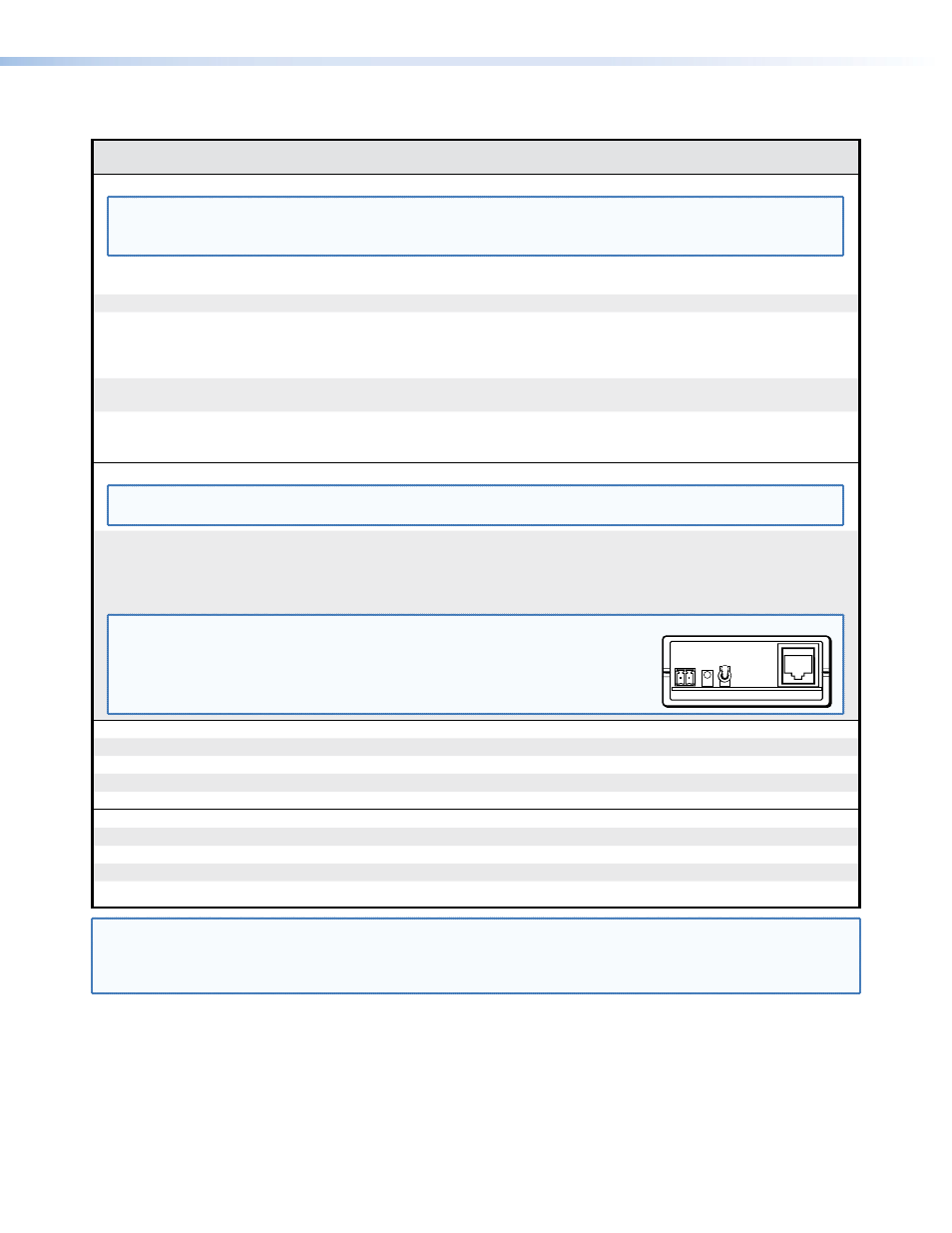
NOTE:
Before issuing the auto calibration command:
1. Disconnect the power and RJ-45 cables at the MTP transmitter connected to X!.
2. Connect the two cables to the optional MTP signal generator.
3. If the input cable is longer than 300 feet (90 m), set the MTP signal generator Pre-
Peak switch on (up when the RJ-45 connector on the signal generator is to the right
as shown). If the cable is shorter than 300 feet (90 m), set the switch down.
Pre-Peak
is on
Manual video peaking adjustment
Set a peaking value
EX!
*
X#
IPEK
}
Ipek
X!
*
X#]
Set the peaking to
X#
.
Increment peaking
EX!
+IPEK
}
Ipek
X!
*
X#]
Increase peaking setting 1 step.
Decrement peaking
EX!
-IPEK
}
Ipek
X!
*
X#]
Decrease peaking setting 1 step.
Show peaking
EX!
IPEK
}
X#]
Manual video level adjustment
Set a level value
EX!
*
X$
ILVL
}
Ilvl
X!
*
X$]
Set the level to
X$
.
Increment level
EX!
+ILVL
}
Ilvl
X!
*
X$]
Increase level setting 1 step.
Decrement level
EX!
-ILVL
}
Ilvl
X!
*
X$]
Decrease level setting 1 step.
Show level
EX!
ILVL
}
X$]
NOTE:
X!
= Input number
1-6
X@
= Threshold
0 = outside threshold
1 = within threshold
X#
= Input peaking range
00 - 65
X$
= Input level range
000 - 255
Command/Response Table for SIS Commands
MTP SW6 • Remote Control
23