Operation – Extron Electronics MTP SW6 User Guide User Manual
Page 19
Operation
AUTO
SWITCH
6
5
4
MTP SW6
MTP SWITCHER
1
MODE
2
NORMAL
3
AUTO
INPUT
RGB
PEAKING
LEVEL
DELAY
RED
GREEN
BLUE
SELECT
ADJUST
1
3
4
5
9
10
8
7
6
2
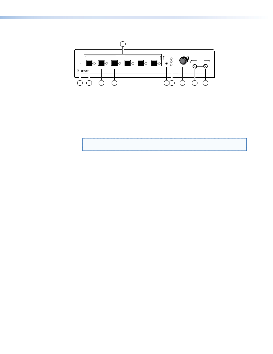
Figure 12.
Switcher’s front panel features
a
Auto Switch LED — When lit, the Auto Switch LED indicates that the switcher is in
auto switch mode. When unlit, the switch is in normal (manual) mode. See
b
Input Buttons and LEDs — When the auto switch mode is off, these buttons select
the input. The LED for the selected input lights.
The LEDs continue to indicate the selected input when the auto switch mode is on. If
no input LED is lit, no input has active sync pulses and no input is selected.
NOTE: Front panel input selection cannot be performed when the auto switch
mode is on (Auto Switch [a] is lit).
c
Mode button — Use this button, with either the Auto or the Normal button, to
manually turn auto switch mode on or off. This control is a secondary function of the
Input 1 button.
d
Normal button — Use this button, with the Mode button, to manually turn auto
switch mode off. This control is a secondary function of the Input 2 button.
e
Auto button — Use this button, with the Mode button, to manually turn auto switch
mode on. This control is a secondary function of the Input 3 button.
f
Delay Select button — This recessed button selects the red, green, or blue video
signal to adjust and resets all three video signals to a skew delay of zero nanoseconds.
Use a Tweeker to press and release this button to select among the red, green, or blue
video signal to adjust. The selected signal is indicated by the Delay Red, Green, and
Blue LEDs (g).
The switcher automatically saves the setting for the video signal that is being
deselected when you push this button or when the selection times out after 10
seconds.
Press and hold this button for approximately 3 seconds to zero the skew delay for red,
green, and blue. The Delay Red, Green, and Blue LEDS (g) all turn off. Release the
button.
g
Delay Red, Green, and Blue LEDs — These LEDs Indicate the video signal that is
selected by the Select button (f) for skew adjustment using the Adjust control (h).
The LED for the selected color flashes when the skew compensation for that color’s
video signal has reached the minimum or maximum limit.
MTP SW6 • Installation and Operation
15