Connectors and settings – Extron Electronics MTP SW6 User Guide User Manual
Page 13
Connectors and Settings
REMOTE
1
2
3
4
5
6
INPUT
PRE-PEAK
ON
OFF
OUTPUT
MONO AUDIO OUTPUT
L
R
POWER
12V
0.5A MAX
MTP SW6
RS-232
INSERT
Tx Rx
SPARE
1
3
7
4
6
5
2
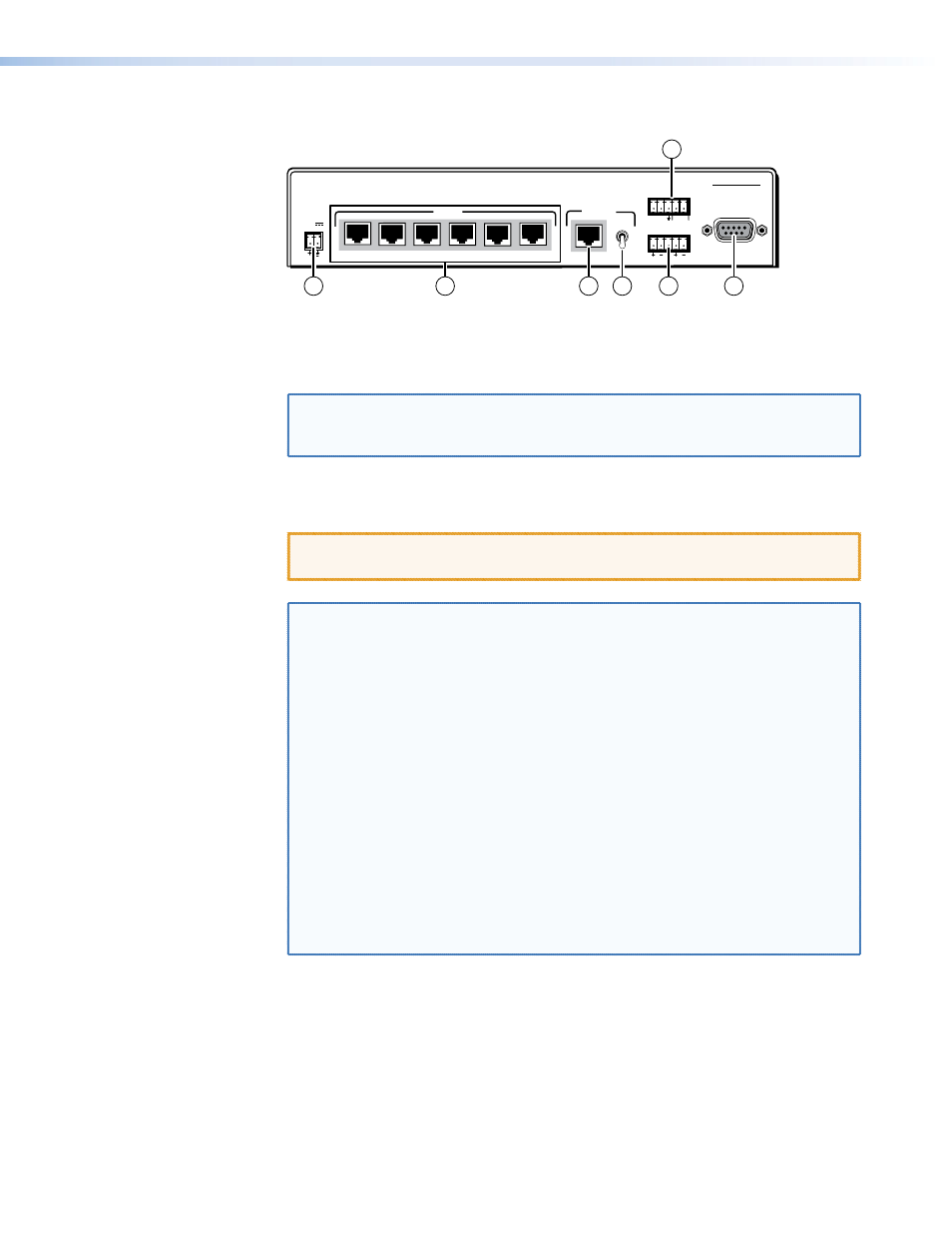
Figure 6.
MTP SW 6 rear panel features
a
DC power connector — Plug the external 12 VDC power supply into this 2-pole
captive screw connector. See
to wire the connectors.
NOTE: The remote power capabilities available with certain MTP models are not
supported by this unit; the transmitter, switcher, and receiver must all be
powered.
b
Input connectors — Connect up to six TP cables from transmitters to these RJ-45
to wire the RJ-45 connectors.
CAUTION: Do not connect this device to a computer data or telecommunications
network.
NOTES: • See
for recommended transmission ranges.
• You must configure the switcher for the appropriate content on the
audio/RS-232 wire pair (pins 3 and 6) for each TP input. See the
Audio/RS-232 TP input (wire pair 3 and 6) configuration
SIS commands.
• For best results, use a combined cable length of at least 50 feet (15 m)
between the transmitter and the receiver on the MTP SW6 output.
• RJ-45 termination with CAT 5, CAT 5e, or CAT 6 cable must comply
with the TIA/EIA T568A or TIA/EIA T568B wiring standards for all
connections.
• RJ-45 termination with Enhanced Skew-Free A/V UTP cable must
comply with TIA/EIA T568A only.
• When low resolution MTPs (S-video and composite video) are the
TP inputs, the MTP SW6 audio circuits are compatible only with
the newer generation, mono audio models. See the appropriate
MTP transmitter/receiver user’s manual to determine which MTP models
you have.
c
Output connector — Connect one end of a terminated TP cable to this RJ-45 female
connector.
Connect the free end of the same TP cable from the switcher to the RJ-45 female
connector on a compatible MTP receiver.
to properly wire the RJ-45 connectors.
MTP SW6 • Installation and Operation
9