Rear panel cabling, Rs-232/remote control, cont’d, Power connection – Extron Electronics Chapter One User Manual
Page 9: Signal input and output connections, Timeout, Using the command/response table
Lanciaxi
xi
xi
xi
xi • Installation
2-3
b
.
Mount the Lanciaxi on the rack shelf, using two
4-40 x 1/8 screws in opposite (diagonal) corners to
secure the case to the shelf.
2
.
If desired, attach a false front panel, or a second ½-rack-
width device to the other side of the shelf.
3
.
Attach the rack shelf to the rack using four 10-32 x ¾” bolts
and four #10 beveled dress washers.
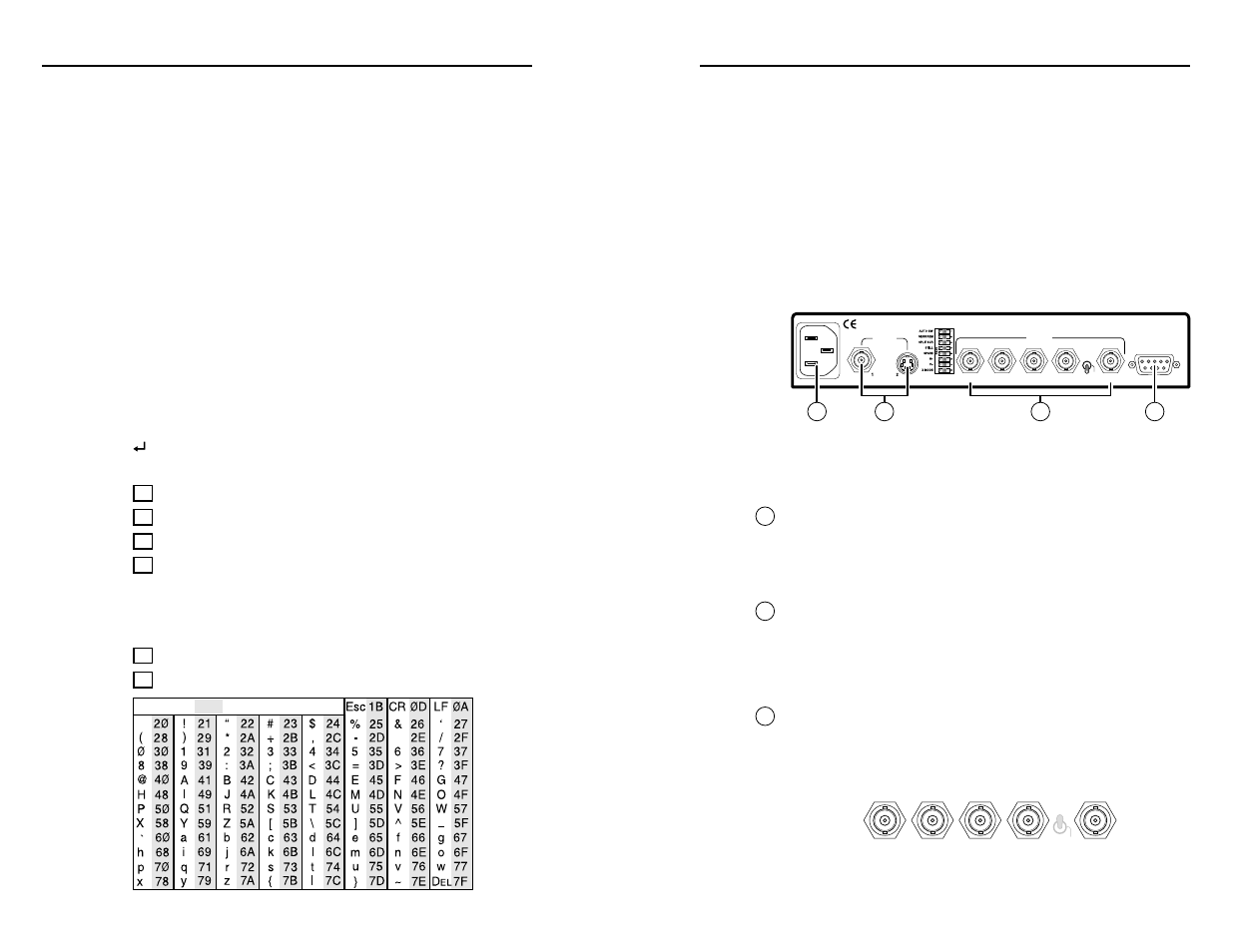
Rear Panel Cabling
All connectors are on the rear panel. Figure 3 shows the cable
connections on the rear panel of the Lanciaxi line doubler.
H
SOG
H/V
R
G
B
H/HV
V
OUTPUT
RS-232
INPUTS
REMOTE
100-240VAC 50/60Hz
100 mA MAX
1
4
3
2
Figure 3 — Rear panel cabling
Power connection
1
AC power connector
— Plug a standard IEC power cord into
this connector to connect the Lanciaxi to a 100 to 240VAC, 50 Hz
or 60 Hz power source.
Signal input and output connections
2
Input connectors
Input 1, composite video connector
— Connect a
composite video device to this BNC connector.
Input 2, S-video connector
— Connect an S-video device to
this 4-pin mini DIN connector.
3
Output connectors
RGBHV video connection
— For RGBHV video, connect
the display to all five BNC connectors. Ensure the H/HV/
SOG switch is in the H position (see “Rear Panel Controls”
in chapter four).
H
SOG
H/V
R
G
B
H/HV
V
Lanciaxi
xi
xi
xi
xi • RS-232/Remote Control
RS-232/Remote Control, cont’d
E01 — Invalid input channel number (out of range)
E06 — Auto-switch active (DIP switch 1 in enable position)
E10 — Invalid command
E13 — Invalid value (out of range)
Timeout
Pauses of 10 seconds or longer between command ASCII
characters result in a timeout. The command operation is
aborted with no other indication.
Using the command/response table
The command/response table is on the next page. Lower case
letters are allowed in the command field only as indicated.
Symbols used throughout the table represent variables in the
command/response fields. Command and response examples
are shown throughout the table. The ASCII to HEX conversion
table below is for use with the command/response table.
Symbol definitions
= CR/LF (carriage return/line feed) (0x0D 0A)
•
= space
X1
= Input number
1 or 2
X2
= Color/tint/contrast value
1 - 127
X3
= Freeze mode state
0 (off) or 1 (on)
X4
= Input type
0 = no input
1 = NTSC 3.58
2 = PAL
3 = NTSC 4.43
4 = SECAM
X5
= Firmware version
x.xx
X6
= Horizontal shift value
1 - 63
ASCII to HEX Conversion Table
Space
4-4