Locking and unlocking the front panel, Setting rgb delay, Using genlock sync – Extron Electronics MPX 423 A User Manual
Page 24: Preliminar y, Operation, cont’d
Operation, cont’d
MPX 423 A • Operation
3-6
PRELIMINAR
Y
Locking and unlocking the front panel
Front panel security lockout prevents accidental switching of inputs from the front
panel. When front panel security lockout is active, the user can only view the ties
in each group; all input buttons and audio functions are locked.
To toggle the front panel lockout on and off, press and hold the I/O button for three
seconds. The Video and Audio LEDs flash twice to indicate a change in the front
panel security status (on or off).
MPX 423 A
MEDIA PRESENTATION MATRIX
VOLUME
I/O
AUDIO
AUDIO OUTPUT 1
VIDEO
MUTE
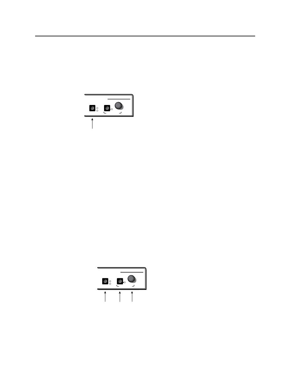
I/O button
When front panel lockout is on, the user can still view the ties by toggling the I/O
and output buttons. The LEDs of the corresponding inputs light according to their
tie modes.
If you attempt to make a tie in lockout mode, the Video and Audio LEDs flash
twice, indicating that no ties can be made from the front panel. RS-232 and
Ethernet controls are still available when the front panel is locked.
Setting RGB delay
The RGB delay feature clears the screen during transition to a new input source,
which prevents a visible glitch from occurring on the output screen. RGB delay can
be set between 0 and 5.0 seconds in 0.5 second increments.
To use the front panel to set an RGB delay:
1.
Select the desired output (1 or 2).
2. Press and hold the I/O and Mute buttons simultaneously for three seconds.
The Video LED and the currently selected Output LED begin flashing.
3.
Turn the volume knob clockwise to increase delay time. Input LEDs 1 - 10
come on one at a time as the volume knob is turned clockwise. Each lit input
LED represents a 0.5 second delay. When RGB delay reaches its maximum of
5 seconds (LEDs 1 through 10 on), the Mute LED flashes.
4.
Press the I/O button to exit.
MPX 423 A
MEDIA PRESENTATION MATRIX
VOLUME
I/O
AUDIO
AUDIO OUTPUT 1
VIDEO
MUTE
I/O
button
Mute
button
Volume
Knob
For setting the RGB delay through RS-232 or Ethernet control, see chapters 4 and 5.
Using Genlock sync
The Genlock sync feature locks the sync generators of multiple devices to a single
source which prevents visible glitches from occurring on the output screen during
transition to a new input source. The source at input 5 provides the Genlock sync
signal to all of the Video group inputs. The source at input 9 provides the Genlock
sync signal to all of the S-Video group inputs. This happens automatically when
inputs are connected to inputs 5 and 9. No configuration is required.