Switcher modes and operation, Introduction to single switcher mode, Introduction to separate switcher mode – Extron Electronics MPX 423 A User Manual
Page 21: Preliminar y, 3 mpx 423 a • operation
3-3
MPX 423 A • Operation
PRELIMINAR
Y
h
Separate switcher mode — This is the secondary function of this button
(see
b
). Press and release this button to select the separate switcher
mode. The associated LED indicates if the separate switcher mode is on
(when flashing). When the Mode button is released, the LED resumes input
indication.
i
Composite video input — Buttons 5 through 8 select the input for the
composite video sections of the MPX unit. The LEDs adjacent to each button
(when lit) indicate which input has been selected for output.
j
S-video input — Buttons 9 through 12 select the input for the S-video group
of the MPX unit. The LEDs adjacent to each button (when lit) indicate which
input has been selected for output 1.
k
Audio mute — This button mutes audio output 1. The LED (when lit)
indicates that audio output 1 is muted.
l
Audio volume — This adjustment knob controls the volume of audio
output 1.
N
The front panel audio controls (mute and volume) only control audio output 1.
Both audio outputs (1 and 2) are controllable through RS-232 or Ethernet/Telnet
via the SIS commands and built-in webpage.
Switcher Modes and Operation
MPX 423 A
MEDIA PRESENTATION MATRIX
VOLUME
1
1
OUTPUTS/
AUDIO
MODE
SINGLE
SEPARATE
INPUTS
COMPUTER
2
2
3
4
1
9
OUTPUTS
INPUTS
S-VIDEO
2
10
11
12
I/O
AUDIO
AUDIO OUTPUT 1
VIDEO
MUTE
1
5
OUTPUTS
INPUTS
VIDEO
2
6
7
8
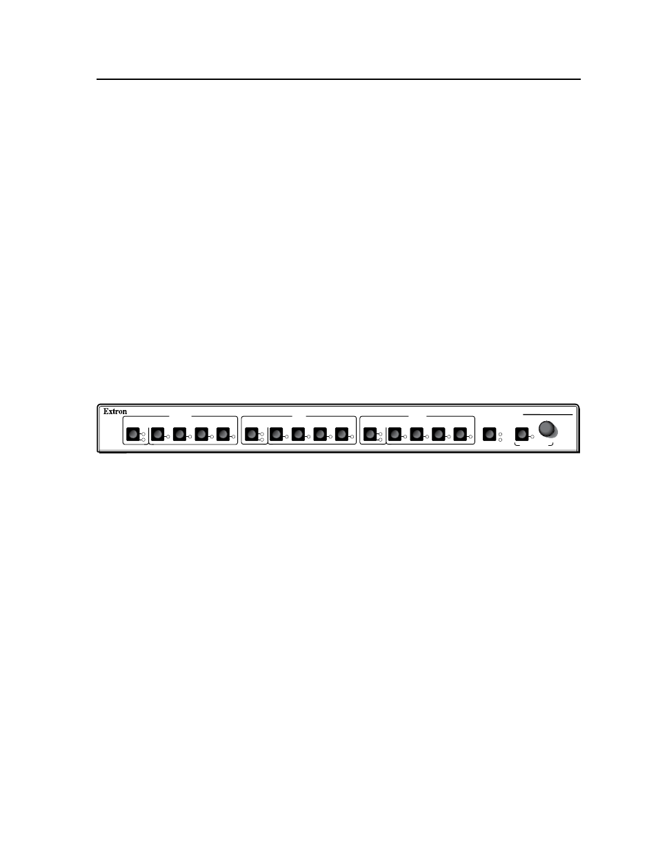
Figure 3-2 — MPX 423 A matrix switcher front panel
Introduction to single switcher mode
In single switcher mode, the switcher emulates a 1 output switcher with 12 inputs.
When a video input signal is tied to an output, it is routed to the output of the same
video signal format. All other video output signals are muted.
The audio operates independently as a 12 inputs to 2 outputs matrix switcher. See
“Audio” later in this chapter for more information.
N
Both audio outputs can be configured in single switcher mode; i.e., the unit
emulates two 1-output switchers with 12 inputs each.
Introduction to separate switcher mode
In separate switcher mode the switcher emulates three 1 output switchers with 4
inputs. There are three input selection groups on the front panel: Computer, Video
(composite), and S-video. These three groups operate independently from each
other, and each of the twelve inputs can only be routed to its own video output
format group.
The audio operates independently as a 12 inputs to 2 outputs matrix switcher.
N
Both audio outputs can be configured in Separate mode; i.e., the unit emulates
three 2-output switchers with 4 inputs each.