Rear panel connectors, Preliminar y, Installation, cont’d – Extron Electronics MPX 423 A User Manual
Page 16
Installation, cont’d
MPX 423 A • Installation
2-4
PRELIMINAR
Y
Rear Panel Connectors
50/60 Hz
100-240V 0.3A
L
1
R
L
2
R
L
3
R
L
4
R
L
5
R
L
6
R
L
7
R
L
8
R
L
9
R
L
10
R
L
11
R
L
12
R
L
1
R
L
2
R
I
N
P
U
T
S
O
U
T
P
U
T
S
C
O
N
T
R
O
L
I
N
P
U
T
S
O
U
T
P
U
T
S
RESET
ACT LINK
RS-232
LAN
1
2
3
4
1
5
6
7
8
1
9
10
11
12
1
2
2
2
COMPUTER IN
COMPUTER OUT
VIDEO IN
S-VIDEO IN
OUT
OUT
COMPUTER
VIDEO
S-VIDEO
VARIABLE
13 14
1
12
2
4
11
7
5
3
6
8
9
10
15
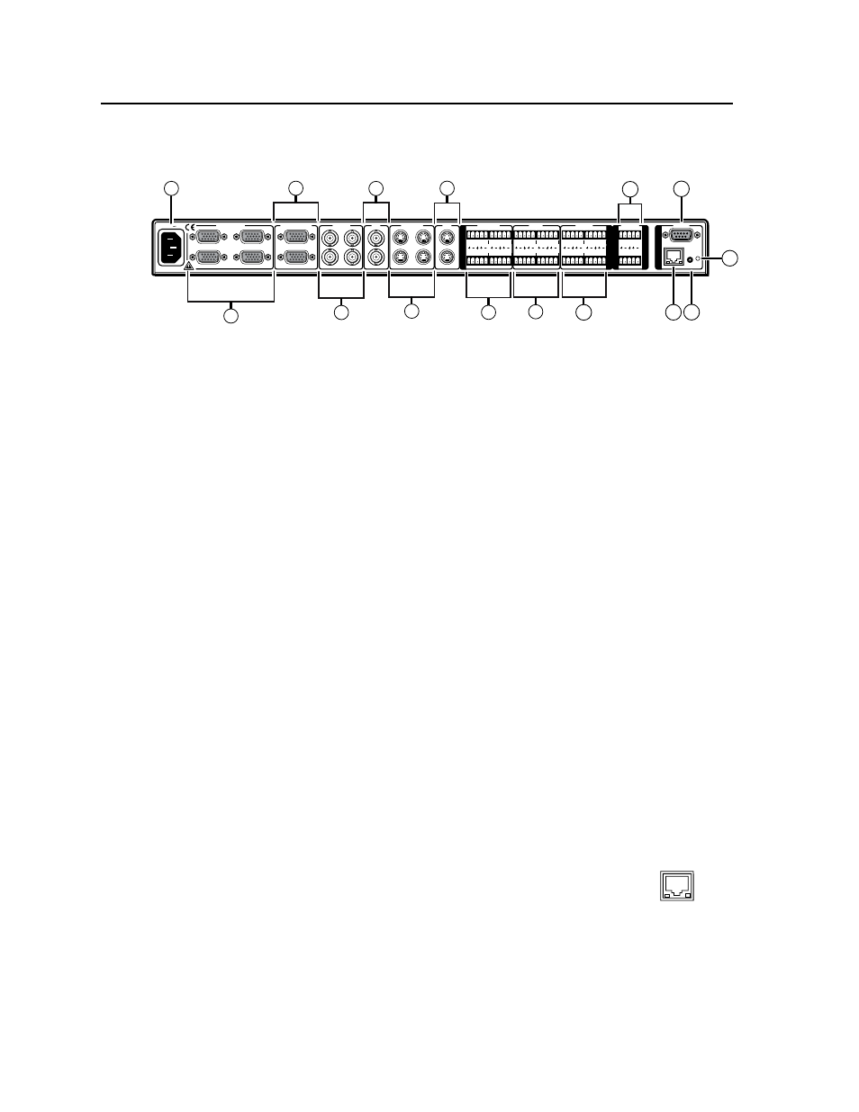
Figure 2-2 — Rear panel of MPX 423 A
a
AC power — Standard AC power connector for a power source of
100 – 240 VAC, operating at 50/60 Hz.
b
VGA input group — Four female 15-pin HD connectors for RGB video input
(numbered 1 to 4).
c
VGA output — Two female 15-pin HD connectors for RGB video output.
d
Composite input group — Four female BNC connectors for composite input
(numbered 5 to 8).
e
Composite output — Two female BNC connectors for composite output.
f
S-video input group — Four female 4-pin mini DIN connectors for S-video
input (numbered 9 to 12).
g
S-video output — Two female 4-pin mini DIN connectors for S-video output.
h
VGA audio input group — Four 3.5 mm female captive screw connectors for
audio input from the VGA group (see “Audio” in chapter 3).
i
Composite audio input group — Four 3.5 mm, female, captive screw
connectors for the composite group input (see “Audio” in chapter 3).
j
S-video audio input group — Four 3.5 mm, female, captive screw connectors
for the S-video group input (see “Audio” in chapter 3).
k
Variable audio output — Two 3.5 mm, female, captive screw connectors
for balanced/unbalanced variable audio output. Only audio output 1 is
variable from the front panel volume knob. Both audio outputs (1 and 2) are
variable through RS-232 or Ethernet/Telnet via the SIS commands and built-in
webpage.
l
RS-232 — One female DB9 connector for a host computer or third party
controller using Extron’s Simple Instruction Set (SIS).
m
LAN Activity LED — A blinking yellow LED indicates LAN activity.
LAN connector
— Plug an RJ-45 jack into this socket to connect
the unit to a computer network. Use a straight-through cable to
connect to a switch, hub, or router.
Link LED
— The green LED lights to indicate a good LAN connection.
n
Reset button — A recessed button that allows for a manual reset using a
Extron Tweeker, pointed stylus or ballpoint pen. The unit can be reset to five
modes (see “Resetting the Unit” in chapter 3).
o
Reset LED — The green LED flashes to show the reset mode indicators and
that power is on (see “Resetting the Unit” in chapter 3).
ACT LINK
LAN