Front panel operation, Preliminar y, Operation – Extron Electronics MPX 423 A User Manual
Page 20
MPX 423 A • Operation
3-2
Operation
PRELIMINAR
Y
Front Panel Operation
MPX 423 A
MEDIA PRESENTATION MATRIX
VOLUME
1
1
OUTPUTS/
AUDIO
MODE
SINGLE
SEPARATE
INPUTS
COMPUTER
2
2
3
4
1
9
OUTPUTS
INPUTS
S-VIDEO
2
10
11
12
I/O
AUDIO
AUDIO OUTPUT 1
VIDEO
MUTE
1
5
OUTPUTS
INPUTS
VIDEO
2
6
7
8
9
10
6
7
8
11
12
4
3
5
1
2
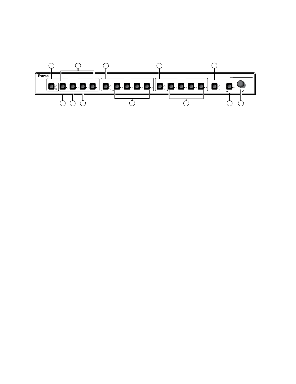
Figure 3-1 — Front panel details of the MPX 423 A matrix switcher
The following sections describe the front panel controls. The controls for the three
independent switchers are grouped by input type.
a
VGA output — These two green LEDs serve four functions:
• Display VGA video output activity.
• Indicate which audio output is active.
• Indicate output selection when setting the switching mode.
• Mute the selected VGA output. See “Muting and un-muting video and/or
audio” later in this chapter.
b
VGA input — Buttons 1 through 4 select the input for the VGA input sections
of the MPX unit. The LEDs adjacent to each button (when lit) indicate which
input has been selected for output.
c
Composite video output — Displays which composite video output (output 1
or output 2) is currently active.
• Mute the selected Composite Video output. See “Muting and un-muting
video and/or audio” later in this chapter.
d
S-video output — Displays which S-video output (output 1 or output 2) is
currently active.
• Mute the selected S-video output. See “Muting and unmuting video
and/or audio” later in this chapter.
e
I/O — This button serves four functions:
• Allows for toggling between video and audio modes, and simultaneous
video/audio functionality. The video and audio LEDs to the right of the
I/O button indicate the current selection; video, audio, or video & audio.
• Provides a method of accessing the Front Panel Security Lockout function.
• Acts as a system reset button.
• Functions with the Mute button to set an RGB delay.
f
Mode — This is the secondary function of this button (see
b
). The mode
function of this button allows the MPX 423 A to be used in either “single” or
“separate” mode.
g
Single switcher mode — This is the secondary function of this button (see
b
). Press and release this button when in “switching mode” (see “Using the
switching mode” later in this chapter) to select the single switcher mode. The
associated LED indicates if the single switcher mode is on (when flashing).
When the Mode button is released, the LED resumes input indication.