Switcher software, Remote control port setup – Extron Electronics IN1502 Setup Guide User Manual
Page 22
Refer also to the IN1502 User’s Manual at www.extron.com.
Remote control port setup
The IN1502 can be remotely controlled via a host computer
or other device (such as a control system) attached to the rear
panel RS-232 9-pin D female connector. RS-232 protocol for this
connection is:
9600 baud
•
no parity
•
1 Stop bit
•
no flow control
•
The control device (host) can use the Extron Simple Instruction
Set (SIS) commands. See Chapter 3 "Serial Communications",
of the IN1502 User's Manual for complete information on serial
control.
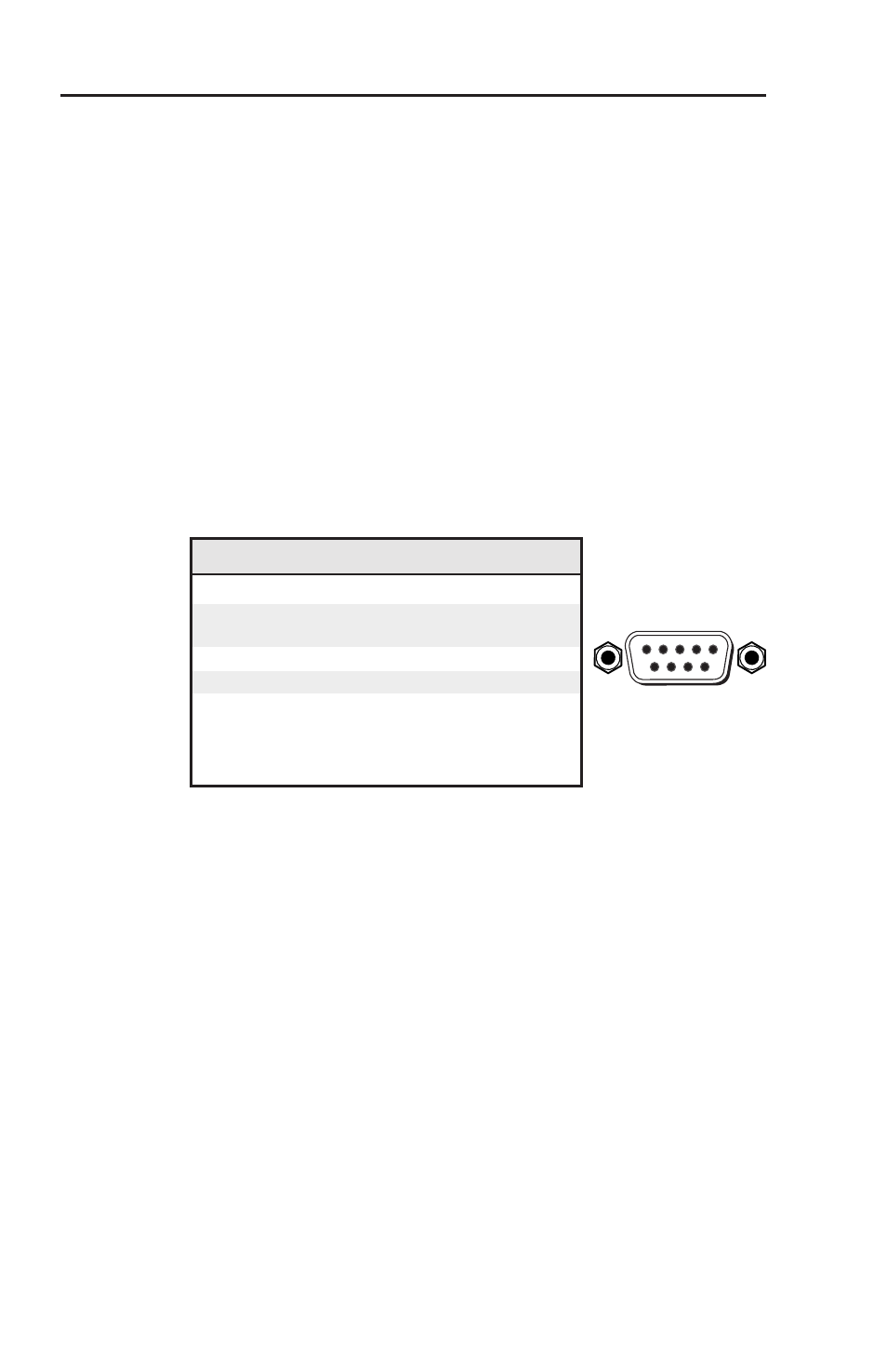
The serial connector also provides a way to select an input
using a remote contact closure device. The connector has the
following pin assignments:
Pin RS-232 function Description
1
–
No connection
2
Tx
Transmit data
3
Rx
Receive data
4
Input #1
Contact closure
5
Gnd
Signal ground
6
Input #2
Contact closure
7
–
No connection
8
–
No connection
9
Hardwired IR
IR input
Contact closure control uses pins not used by the RS-232
interface. To select an input using a contact closure device,
momentarily short the pin for the desired input to ground
(pin 5). To force one of the inputs to always be selected, leave
the short in place.
N
The short overrides front panel input selections.
DB9 Pin Locations
Female
5
1
9
6
IN1502 • Switcher Software
Switcher Software
3-2