Cabling the scaler, Optimizing the system for a dvd player, Cabling the scaler – Extron Electronics IN1502 Setup Guide User Manual
Page 10: Optimizing the system for a dvd player, Introduction and installation, In1502 rear panel connectors, In1502 • introduction
1-4
Refer also to the IN1502 User’s Manual at www.extron.com.
Cabling the scaler
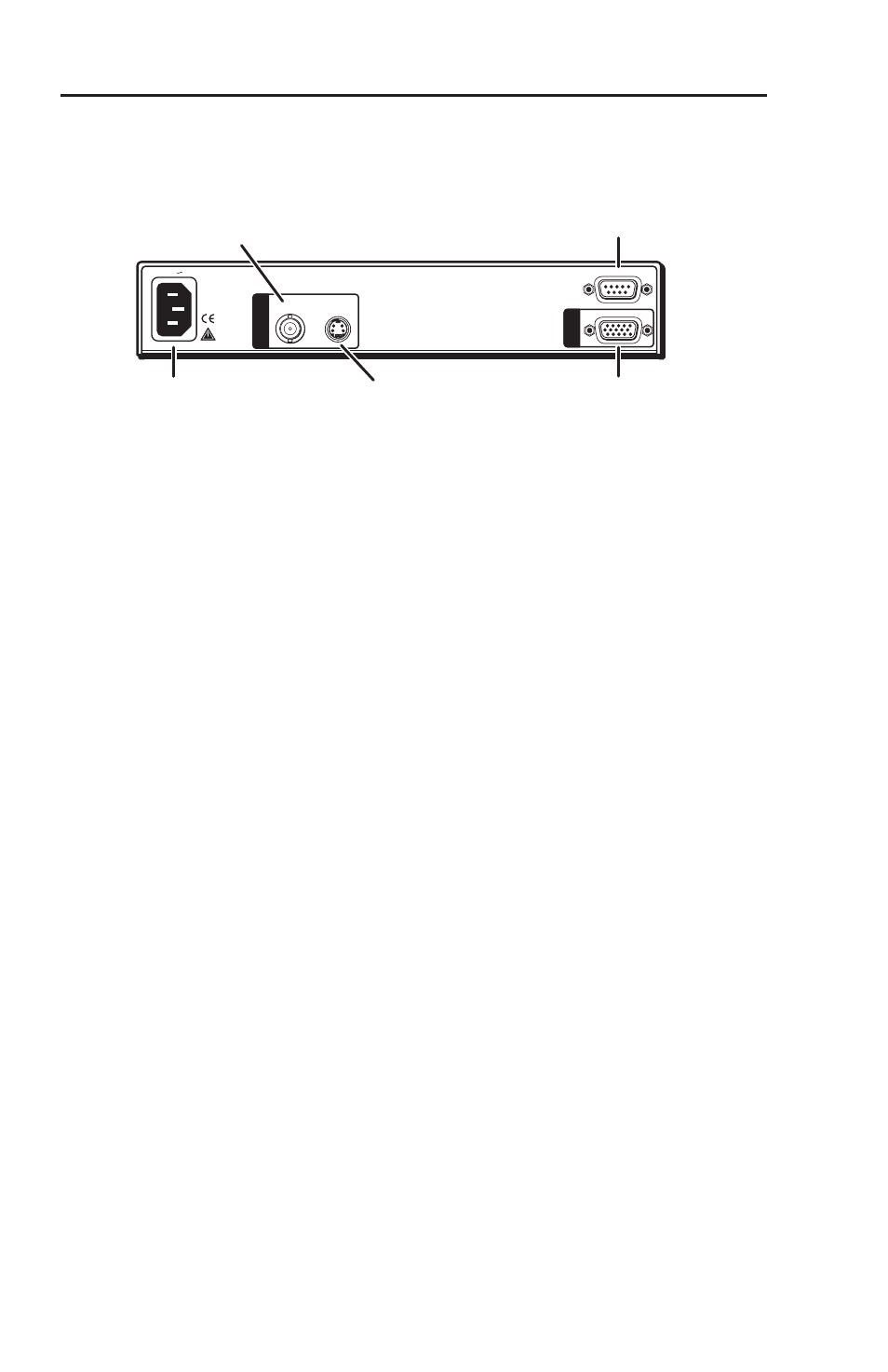
Refer to the following diagram for connections to the IN1502.
50/60 Hz
1
2
REMOTE
RGB
S-VIDEO
COMPOSITE
100-240V 0.3A
I
N
P
U
T
S
O
U
T
AC power connector
Plug a standard IEC power cord to
a 100 to 240 VAC, 50 Hz or 60 Hz
power source. The front panel LCD
display and input selection LEDs
light during power-up.
Video input 1: Composite video
Connect a composite video signal
to this female BNC connector.
Video input 2: S-video
Connect an S-video signal
to this 4-pin mini-DIN
female connector.
RGB 15-pin HD video output
Connect an RGB video display.
Remote (RS-232/contact closure) 9-pin port
Provides two-way RS 232 communication and
contact closure control.
IN1502 rear panel connectors
Optimizing the System for a DVD Player
To obtain optimal performance when using a DVD as a
video source, Extron recommends the DVD player be set to
output an aspect ratio of 16:9 and not 4:3. Since all DVDs are
mastered as 16:9, if set up for 4:3 the player will internally
scale and compress the signal. This will defeat the automatic
3:2 pulldown detection in the IN1502.
Sizing adjustments to correct aspect ratio should be done using
the IN1502 controls.
IN1502 • Introduction
Introduction and Installation