Command and response table for sis commands – Extron Electronics FOX SW8 User Guide User Manual
Page 17
FOX SW8 • Remote Control
11
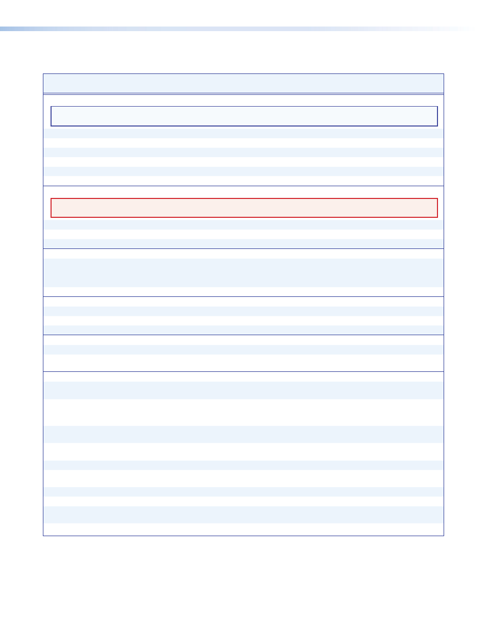
Command and Response Table for SIS Commands
Command Function
ASCII Command
(Host to Unit)
Response
(Unit to Host)
Additional description
Input selection
NOTE
:
The three command codes in the input selection commands and view input commands; !, &, and %; can be used
interchangeably.
Select input
X!
!
In
X!
•All
]
Select input
X!
to output.
Select input
X!
&
In
X!
•RGB
]
Select input
X!
to output.
Select input
X!
%
In
X!
•Vid
]
Select input
X!
to output.
View input
!
X!]
Input
X!
is selected for output.
View input
&
X!]
Input
X!
is selected for output.
View input
%
X!]
Input
X!
is selected for output.
Channel mute
WARNING: Risk of serious physical injury: The channel mute command mutes the data on the switched output only. The output
continues to emit light, which may be harmful to the eyes. The mute function has no affect on the looped-through outputs.
Mute output
1B
Vmt1
]
Blank data on switched output.
Unmute output
0B
Vmt0
]
Output data on switched output.
Show video mute status
B
X@]
Switched output mute status is
X@
.
Reclocking
Set reclocker mode
08*
X&
=
Rte08*
X&]
Set the reclocker mode to
X&
.
Example:
08*0=
Rte08*00
]
Set the output reclocker mode to bypass (do not reclock).
Example:
08*0=
Rte08*03
]
Set the output reclocker mode to 4.25 Gbps (
default).
Show reclocker mode
08=
X&]
Front panel security lockout (executive mode)
Lock front panel
1
X
Exe1
]
Inputs cannot be selected from the front panel.
Unlock front panel
0X
Exe0
]
Inputs can be selected from the front panel.
Show lock status
X
X@]
Front panel lock status is
X@
.
Resets
Reset mute
E
ZZ
}
Zpz
]
Unmute the output.
Reset whole switcher
E
ZXXX
}
Zpx
]
Unmute the output, unlock the front panel, and select
input 1.
Information Requests and Unit Name
Information request
I
In
X!
•Vmt
X@]
In
X!
indicates the selected input. Vmt
X@
indicates the
output mute status (
0
= unmuted,
1
= muted)..
Show firmware version
Q
X$]
X$
is the firmware version.
Example:
Q
1.23
]
The factory-installed FOX SW8 controller firmware
version is 1.23 (sample value only).
Request part number
N
60-1172-nn
]
nn indicates the transmission mode.
01
= multimode,
02
= singlemode.
Show input connections
status
0LS
X%
1
X%
2
X%
3
X%
4
...
X%
8
]
Each
X%
indicates the status of an input,
0
= no light on this input,
1
= light received.
Show temperature
20S
X^]
X^
= degrees Fahrenheit.
Show transceiver module
status
0*1I
X#
1
X#
2
X#
3
X#
4
...
X#
8
]
Show all installed transceiver modules.
0
= none,
1
= multimode,
2
= singlemode.
Set switcher name
EX*
CN
}
Ipn•
X*]
Set the switcher name to
X*
.
Example:
E
Switcher_1CN
}
Ipn•Switcher-1
]
Set the switcher name to “Switcher-1”.
Set switcher name to
factory default
E
•CN
}
Ipn•FOX-SW8
]
Restore the factory default name.
View switcher name
E
CN
}
X*]