Installation and operation, Rear panel connections – Extron Electronics FOX SW8 User Guide User Manual
Page 10
FOX SW8 • Installation and Operation
4
Installation and
Operation
The topics covered in this section are:
•
•
Front Panel Configuration Port
•
Controls, Indicators, and Operation
Rear Panel Connections
100-240V 0.3A
50/60 Hz
RS-232
Tx Rx
FOX SW8
OPTICAL INPUTS
LOOP IN
LOOP IN
LOOP IN
LOOP IN
LOOP IN
LOOP IN
LOOP IN
OUT IN
1
2
3
4
5
6
7
8
5
1
3
4
2
3
3
2
3
3
2
3
3
2
2
2
2
2
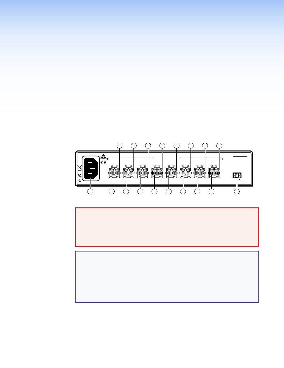
Figure 2.
FOX SW8 Connectors
WARNING: Risk of serious physical injury: The FOX SW8 outputs continuous
invisible light, which may be harmful to the eyes; use with caution.
•
Do not look into the rear panel fiber optic cable connectors or into the fiber optic
cables themselves.
•
Plug the attached dust caps into the optical transceivers when the fiber cable is
unplugged.
NOTES:
•
Singlemode and multimode devices are not interchangeable. Ensure that the
connected transmitting and receiving devices are compatible with the FOX SW8.
•
Ensure that you use the proper fiber cable for your system. Typically, singlemode
fiber has a yellow jacket and multimode cable has an orange or aqua jacket.
•
In this guide, the term “sending connector” refers to an LC connector on a device
that outputs a fiber optic signal. The term “receiving connector” refers to an LC
connector that receives an optical signal.
a
AC power connector — Plug a standard IEC power cord into this connector to
connect the FOX SW8 to a 100 VAC to 240 VAC, 50-60 Hz power source.