Operation, Figure 27. non-decora model control and indicator, Figure 28. decora model power indicator – Extron Electronics DVI 201 User Guide User Manual
Page 30
Operation
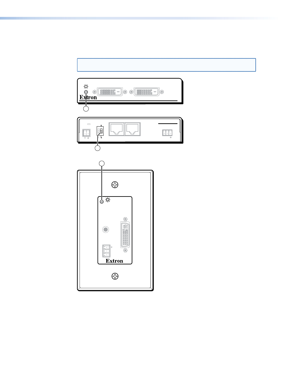
Figure 27 shows the DDC control and power indicator on the non-Decora transmitter.
Figure 28 shows the power indicator on the Decora transmitter.
NOTE: All transmitter and receiver models have power indicators in the locations
shown.
DVI 200 Tx SERIES
DVI INPUT
LOCAL OUTPUT
POWER
12V
0.4A MAX
DVI 201 Tx
RS-232
PASS THRU
Tx Rx
DDC ROUTE
1
2
REMOTE
SPARE
LOCAL
2
1
DVI 201 Tx Transmitter Rear Panel
DVI 201 Tx Transmitter Front Panel
Figure 27.
Non-Decora Model Control and Indicator
INPUT
Rx
Tx
RS-232
PASS THRU
DVI
AUDIO L+R
1
DVI 201 A D Tx Transmitter Front Panel
Figure 28.
Decora Model Power Indicator
DVI 201 • Installation and Operation
26
See also other documents in the category Extron Electronics Accessories for video:
- FOX Matrix 3200 (132 pages)
- ADA 2-4-6 Series (3 pages)
- ADA 6 Component (2 pages)
- AVT 100 (37 pages)
- AVT 200HD Setup Guide (4 pages)
- AVT 200HD User Guide (118 pages)
- AVTrac (482) User Guide (28 pages)
- CAT 5 Receivers (15 pages)
- CAT 5 Transmitters (15 pages)
- CD 400 (3 pages)
- CD 800 (15 pages)
- CD 900 (19 pages)
- CD 100 (18 pages)
- CSVEQ 100 D (38 pages)
- CSVEQ 100 D (2 pages)
- DA RGB_YUV Series (17 pages)
- CVEQ1, CVEQ1 WM, CVEQ1 AAP (17 pages)
- CVEQ_SVEQ 100 Series Setup Guide (2 pages)
- CVDA 6 EQ MX (3 pages)
- CVDA 6 EQ MX (2 pages)
- CVC 300 (8 pages)
- CVC 200 (4 pages)
- CVC 100 (2 pages)
- DDS 402 (54 pages)
- DDS 100 (54 pages)
- DA AV EQ Series (2 pages)
- DVC 501 SD User Guide (38 pages)
- DVC 501 SD Setup Guide (2 pages)
- DTP T USW 333 User Guide (26 pages)
- DTP T USW 333 Setup Guide (4 pages)
- DTP T USW 233 User Guide (26 pages)
- DTP T USW 233 Setup Guide (4 pages)
- DTP HDMI 330 User Guide (19 pages)
- DTP HDMI 330 Setup Guide (2 pages)
- DTP HDMI 301 User Guide (23 pages)
- DTP HDMI 301 Setup Guide (2 pages)
- DTP HDMI 230 User Guide (19 pages)
- DTP HDMI 230 Setup Guide (2 pages)
- DTP HDMI 230 D User Guide (22 pages)
- DTP DVI 330 User Guide (19 pages)
- DTP DVI 330 Setup Guide (2 pages)
- DTP DVI 301 User Guide (23 pages)
- DTP DVI 301 Setup Guide (2 pages)
- DTP DVI 230 User Guide (19 pages)
- DTP DVI 230 Setup Guide (2 pages)