Connections, Transmitter connections, Ear of the unit. see – Extron Electronics DVI 201 User Guide User Manual
Page 20: Ont panel devices (see
Connections
Transmitter Connections
The wall-mountable transmitter is in an enclosure that can be mounted in UL standard
wall boxes with Decora-style face plates. The rack-mountable transmitter is in a quarter
rack width enclosure.
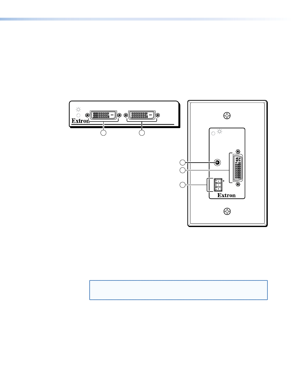
Figure 13 shows the front panel of the DVI 201 A D Tx.
shows the rear panel of both DVI 201 Tx models.
DVI 200 Tx Series
DVI INPUT
LOCAL OUTPUT
DVI 201 Tx Front Panel
DVI 201 A D Tx Front Panel
INPUT
Rx
Tx
RS-232
PASS THRU
DVI
AUDIO L+R
4
2
1
1
3
Figure 13.
DVI 201 Tx Front Panel Connectors
a
DVI Input connector — Connect a DVI cable between this port and the DVI
output port of the digital video source. See
assignments.
b
Local output (DVI 201 Tx ([non-Decora] only) — If desired, connect a DVI
monitor for local monitoring of the input digital image. See
NOTE: In a system where the local output is not used, ensure that you power up
the end display first before the video source. Route the DDC to the remote
end (see the DDC Route DIP switch [
DVI 201 • Installation and Operation
16