Figure 14 – Extron Electronics DVI 201 User Guide User Manual
Page 21
POWER
12V
0.4A MAX
DVI 201 Tx
RS-232
PASS THRU
Tx Rx
DDC ROUTE
1
2
REMOTE
SPARE
LOCAL
PO
WER
12V
0.4A MAX
L
A
UDIO
OUTPUT
R
DO NOT
CONNECT
TO LAN
1
2
DVI 201
A D Tx
O
U
T
P
U
T
S
5
6
4
7
DVI 201 Tx Rear Panel
DVI 201 A D Tx Rear Panel
6
5
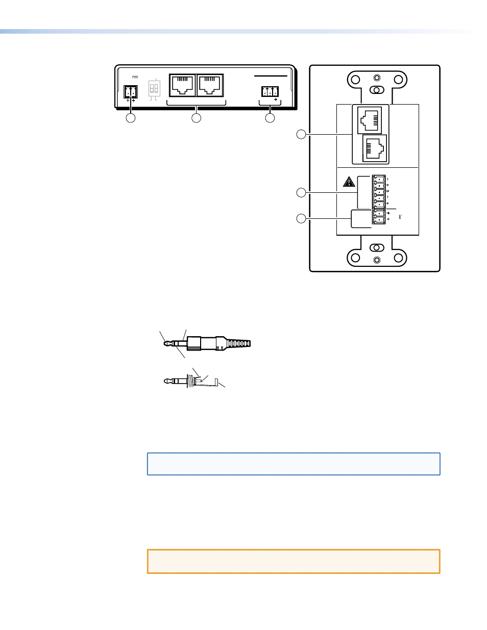
Figure 14.
DVI 201 Tx Rear Panel Connectors
c
Audio input (DVI 201 A D Tx [Decora] only) — Connect an unbalanced stereo
audio source to this 3.5 mm mini stereo jack for unbalanced audio input. Figure 15
shows how to wire the audio plug.
Tip (L+)
Sleeve (Gnd)
Tip (L+)
Ring (R+)
Sleeve (Gnd)
Figure 15.
Audio Input Connector Wiring
d
RS-232 (Control) Pass Thru connector — Connect a serial communications
port to this 3.5 mm, 3-pole captive screw connector for bidirectional RS-232
communication. See
to wire the connector.
NOTE: The RS-232 connector can also transmit one-way modulated infrared (IR)
signals. See
Modulated IR Pass Through Application
e
DC power input connector — Plug the included external 12 VDC power supply
into either this 2-pole connector or the power input connector on the receiver
(
to wire the connector.
f
Transmitter output ports — Connect one end of two separate TP cables to these
RJ-45 female connectors on the transmitter.
CAUTION: Do not connect this device to a computer data or telecommunications
network.
DVI 201 • Installation and Operation
17