Tp cable termination – Extron Electronics DVI 201 User Guide User Manual
Page 26
TP cable termination
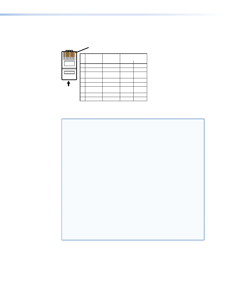
Figure 21 details the recommended termination of TP cables with RJ-45 connectors in
accordance with either the TIA/EIA T 568A or the TIA/EIA T 568B wiring standard.
5
Pin
1
2
3
6
7
8
4
N
Terminate both ends of both cables identically, in accordance with
either the TIA/EIA T 568A or the TIA/EIA T 568B wiring standard.
Wire color
White-green
Green
White-orange
White-blue
Orange
White-brown
Brown
Blue
Data 0+
Data 0–
Data 1–
ID Clock–
Data 2+
Data 2–
Wire color
White-green
Green
White-orange
White-blue
Orange
White-brown
Brown
Signal
TIA/EIA T
568 A
TIA/EIA T
568 B
RJ-45 #1
ID Clock+
Data 1+
Blue
CEC
HPD
RS-232
TX
+12 V
RS-232
RX
DDC data
Ground
RJ-45 #2
DDC Clk
12345678
Insert
Twisted
Pair Wires
Pins:
RJ-45
Connector
Figure 21.
TP Cable Termination
NOTES: • RJ-45 termination with CAT 5, CAT 5e, CAT 6, or DTP26 cable must
comply with the TIA/EIA T 568A or TIA/EIA T 568B wiring standard for all
connections.
• Extron recommends 28AWG to 24AWG TP cable for the RJ-45 connectors.
• Do not use Extron UTP23SF-4 Enhanced Skew-Free
™
A/V UTP cable to link
the transmitter and receiver. Skew-free A/V cable was designed for most
Extron TP transmitter/receiver applications, but the DVI 201 Tx/Rx does not
work properly with this cable.
• In order to fit in the junction box, the TP cables and RJ-45 connectors
should not have a boot installed.
• Connect transmitter output 1 to receiver input 1. Connect transmitter
output 2 to receiver input 2.
• If necessary, test for proper cable connection (output 1 to input 1, output 2
to input 2) as follows:
1. Plug both TP cables into the powered unit.
2. Momentarily connect either of the cables on the opposite end into the
“2” connector on the unpowered unit.
If the Power LED on the unpowered unit is lit, the connection is correct.
If the Power LED on the unpowered unit is not lit, unplug the connector
on the unpowered end and connect the other cable to the “2”
connector.
• The transmitter and receiver pair works with unshielded twisted pair (UTP)
or shielded twisted pair (STP) cables; but, to ensure FCC Class A and CE
compliance, STP cables are required. See
DVI 201 • Installation and Operation
22