Xylem 19 001 300 R2 Silent Storm VFD Pumping System OMRON Touch Screen Display Manual User Manual
Page 51
© 2013 Flowtronex
How Do I?
47
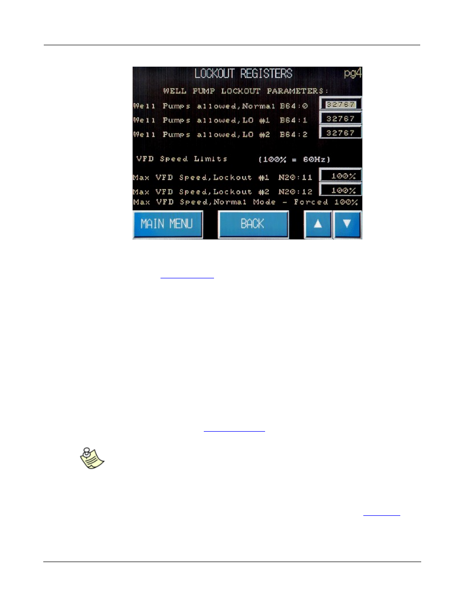
Lockout Registers page 4 screen defines whether well pump(s) can be used within normal and lockout
modes of operation. A well pump can be a transfer out (or de-watering) pump, or a transfer in (lake fill)
pump. Please refer to the
Lake fill section
of this manual to learn how to define the operating
parameters for the well (lake fill) pump(s).
· B64:0 defines the Well Pumps allowed under Normal operation.
· B64:1 defines the Well Pumps allowed under Lockout 1 operation.
· B64:2 defines the Well Pumps allowed under Lockout 2 operation.
The other function this screen serves is to allow you to restrict the maximum VFD speed during the
lockout period. The default value should be 100%. This function is rarely used but could come in handy
when electrical usage is restricted. You could set this value to something like 60 - 80 % and limit your
current draw that way.
· N20:11 defines the Maximum VFD Speed allowed under Lockout 1 operation as a percent.
· N20:12 defines the Maximum VFD Speed allowed under Lockout 2 operation as a percent.
· Tap the value field next to any of these registers and the calculator/keypad pops-over the screen.
Enter or edit the value. (See also,
Calculator/Keypad
.)
Note:
Caution should be exercised when using this option. If you set the Maximum speed
too low, the pump might not be able to attain the desired setpoint. Shutting down
on a low discharge fault is a distinct possibility. It is suggested that you manually
operate the drive at that speed to determine what pressure and flow it will sustain.
· Optionally, press the Main Menu touch key to return to the Main Menu. (See also,
Main Menu
.)
· Optionally, press Back to return to the previous screen.
· Press the up arrow (▲) in the bottom right corner of the screen to open the previous screen,