Centripro, Residential water systems, Wire centripro motor data – Xylem BMAID R4 User Manual
Page 8
PAGE 8
Residential Water Systems
CentriPro
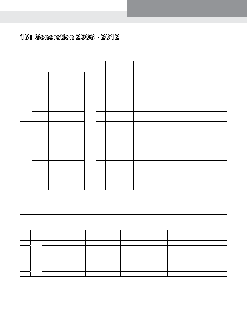
3-wIrE, SINGlE phaSE 4" motorS - ElECtrICal Data, 60 hErtz, 3450 rpm
1St Generation 2008 - 2012
3-wIrE CENtrIpro motor Data
full load
Service factor locked
rotor
amps
winding
resistance
required
Control box
type
order
No.
rJ ref.
#
hp kw Volts Sf
amps watts amps watts
main
(b-y)
Start
(r-y)
3-
Wire
with
Q.D.
Cap.
Start
Box
M05411 50C301 0.5 0.37 115
1.6
Y – 11.0
B – 11.0
R – 0
733
Y – 12.6
B – 12.6
R – 0
1021
49.6
0.9 -
1.6
5.7 -
7.0
CB05411
M05412 50C311 0.5 0.37
230
1.6
Y – 5.5
B – 5.5
R – 0
745
Y – 6.3
B – 6.3
R – 0
1033
22.3
4.2 -
4.9
17.4 -
18.7
CB05412
M07412 75C311 0.75 0.55
1.5
Y – 7.2
B – 7.2
R – 0
1014
Y – 8.3
B – 8.3
R – 0
1381
32.0
2.6 -
3.6
11.8 -
13.0
CB07412
M10412 100C311 1.0 0.75
1.4
Y – 8.4
B – 8.4
R – 0
1267
Y – 9.7
B – 9.7
R – 0
1672
41.2
2.2 -
3.2
11.3 -
12.3
CB10412
3-
Wire
with
CSCR
(CR)
or
Mag-
netic
Con-
tactor
(MC)
Con-
trol
Box
M05412 50C311 0.5 0.37
1.6
Y – 4.1
B – 4.1
R – 2.2
720
Y – 4.9
B – 4.4
R – 2.1
955
22.3
4.2 -
4.9
17.4 -
18.7
CB05412CR
M07412 75C311 0.75 0.55
1.5
Y – 5.1
B – 5.0
R – 3.2
1000
Y – 6.3
B – 5.6
R – 3.1
1300
32.0
2.6 -
3.6
11.8 -
13.0
CB07412CR
M10412 100C311 1.0 0.75
1.4
Y – 6.1
B – 5.7
R – 3.3
1205
Y – 7.2
B – 6.3
R – 3.3
1530
41.2
2.2 -
3.2
11.3 -
12.3
CB10412CR
M15412 150C311 1.5
1.1
1.3
Y – 9.7
B – 9.5
R – 1.4
1693
Y – 11.1
B – 11.0
R – 1.3
2187
47.8
1.6 -
2.3
7.9 -
8.7
CB15412CR or
CB15412MC
M20412 200C311 2.0
1.5
1.25
Y – 9.9
B – 9.1
R – 2.6
2170
Y – 12.2
B – 11.7
R – 2.6
2660
49.4
1.6 -
2.2
10.8 -
12.0
CB20412CR or
CB20412MC
M30412 300C311 3.0
2.2
1.15
Y – 14.3
B – 12.0
R – 5.7
3170
Y – 16.5
B – 13.9
R – 5.6
3620
76.4
1.1 -
1.4
2.0 -
2.5
CB30412CR or
CB30412MC
M50412 500C311 5.0
3.7
1.15
Y – 24.0
B – 19.1
R – 10.2
5300
Y – 27.0
B – 22.0
R – 10.0
6030
101.0
0.62 -
0.76
1.36 -
1.66
CB50412CR or
CB50412MC
GENEratIoN I - 3-wIrE, SINGlE phaSE motor wIrE SIzING Chart
Centripro motor lead lengths - 3-wire motors, 1Ø, 4" motors
Based on Service Factor Amps, 30º C Ambient and 5% Voltage Drop
motor rating
60º C and 75º C Insulation - awG Copper wire Size
hp Volts kw fla Sfa
14
12
10
8
6
4
3
2
1
1/0
2/0
3/0
4/0
0.5
115
0.37
11
12.6
87
138
221
349
544
867
1090
1376
1734
2188
2761
3485
4391
0.5
230
0.37
5.5
6.3
348
553
883
1398
2175
3467
4359
5505
6935
8753 11044 13942 17564
0.75
0.55
7.2
8.3
264
420
670
1061
1651
2632
3309
4178
5264
6644
8383 10582 13332
1.0
0.75
8.4
9.7
226
359
573
908
1413
2252
2831
3575
4504
5685
7173
9055 11408
1.5
1.1
9.7
11.1
197
314
501
793
1234
1968
2474
3124
3936
4968
6268
7913
9969
2.0
1.5
9.9
12.2
180
286
456
722
1123
1790
2251
2843
3581
4520
5703
7199
9070
3.0
2.2
14.3 16.5
133
211
337
534
830
1324
1664
2102
2648
3342
4217
5323
6706
5.0
3.7
24
27
206
326
507
809
1017
1284
1618
2042
2577
3253
Tables based on values from NEC, Tables 310.16 and 310.17 and NEC, Chapter 9, Table 8 Conductor Properties.
NOTE: Motors and control boxes are designed to operate on 230V systems. Systems with low line voltage, between 200 – 207 volts require
the next larger cable size than shown in the 230V charts. If using a 3-wire motor with control box on a low voltage application switch
to a 208V start relay. The 208V start relay order numbers are found on control box repair part charts in this manual.
Temperature Conversions: 20º C = 68º F, 30º C = 86º F, 60º C = 140º F, 75º C = 167º F, 90º C = 194º F