Centripro, Residential water systems, Aquavar solo data – Xylem BMAID R4 User Manual
Page 28
PAGE 28
Residential Water Systems
CentriPro
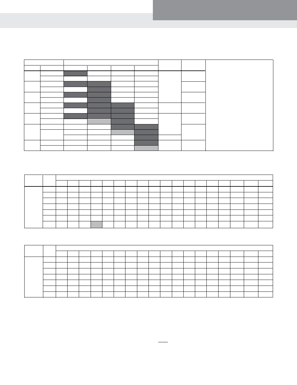
aquaVar Solo Data
Service Entrance to Controller
Controller motor
Copper wire Size 75ºC Insulation Exposed to a maximum of 50ºC (122ºf) ambient temperature ⑥
Input
hp 14 12 10 8 6 4 3 2 1 1/0 2/0 3/0 4/0 250 300 350 400 500
½ 366 583 925 1336 2107 3345 4175 5267 6637 8364
¾ 279 445 706 1020 1608 2552 3186 4019 5065 6383 8055
1
226 360 571 824 1300 2064 2576 3250 4095 5161 6513 8201
1½ * 286 455 657 1036 1644 2052 2589 3262 4111 5188 6533 8236 9710
2
*
* 331 478 754 1197 1495 1886 2376 2995 3779 4759 5999 7073 8455 9852
3 * * 246 355 561 890 1111 1401 1766 2225 2808 3536 4458 5256 6283 7321 8343
5 * * *
218 343 545 680 858 1081 1363 1720 2165 2730 3219 3847 4483 5109 6348
230V
1 PH
Controller to motor
Controller motor
Copper wire Size 75ºC Insulation Exposed to a maximum of 50ºC (122ºf) ambient temperature ⑥
output
hp 14
12
10 8 6 4 3 2 1 1/0
2/0
3/0
4/0
250
300
350 400 500
½ 905 1442 2290 3306 5213 8276
¾ 690 1100 1748 2523 3978 6316 7884 9945
1
558 890 1413 2040 3216 5106 6375 8041
1½ 445 709 1126 1625 2562 4068 5078 6406 8072
2
324 516 820 1184 1866 2963 3699 4666 5879 7410 9351
3
241 384 609 880 1387 2202 2749 3467 4369 5506 6949 8750
5
* 235 373 539 849 1348 1683 2123 2675 3372 4255 5358 6755 7964 9520
⑤
Reduce lengths by 13% for 200 V systems.
⑥
Lengths in bold require 90ºC wire. Shading indicates 40º C maximum ambient.
* Wire does not meet the N.E.C. ampacity requirement.
230V
3 PH
The lengths in each of the Wire Sizing tables represent 100% of the allowable voltage drop when motor is running at full load.
When sizing wire, the voltage drop of each wire segment must be included. The total must not exceed 100% of the allow-
able drop. Take for example a 1.5 HP motor with a distance from Service Entrance to Controller of 100' and 500' between the
Controller and Motor.
• Service Entrance to Controller = 100' of 10 AWG (100/455) = 22 % (455' is from the S.E. to Controller chart)
• Controller to Motor
= 500' of 12 AWG (500/709) = 71 % (709' is from the Controller to Motor chart)
Total Drop (must be ≤ 100%) 93 %
If the distance from the Controller to Motor was 600' (600/709) = 85% + 22% = 107%, we would need to use #10 wire for that
segment, ex. 600/1126 = 53% + 22% (for 100' of #10) = 75% which is acceptable. It is also acceptable to use different wire
sizes for the Buried and Well sections of wire.
WiRE Sizing – MAxiMuM CABlE lEngthS in FEEt to liMit VoltAgE DRoP to 5% FoR 230 V SyStEMS ⑤
CoNtrollEr, brEakEr, GENErator SIzING
motor
Controller model ➁ Circuit Generator
➃
hp Voltage
➀
1aS15 3aS20 3aS30 3aS50 breaker ➂ (Va)
½
230
2200
200
¾
230
15
2900
200
1
230
3500
200
1½
230
20
4400
200
2
230
6100
200
30
230
3
200
8100
40
5
230
50
13300
200
➀
Supply voltage must be 196 VAC – 265
VAC.
➁
Shaded areas indicate which controller
models can be used with which motors.
Lighter shading indicates combina-
tions where controller will limit peak
performance to 85% of catalog value for
pump/motor.
➂
Circuit Breaker or Dual Element Time Delay
Fuse Size (Amps) protecting branch circuit
supplying controller.
➃
Minimum size of single phase 240 V
generator required.