Ap7173 – Diodes AP7173 User Manual
Page 11
AP7173
1.5A LOW DROPOUT LINEAR REGULATOR WITH
PROGRAMMABLE SOFT-START
AP7173
Document number: DS31369 Rev. 9 - 2
1 of 15
April 2011
© Diodes Incorporated
Application Notes
(Continued)
PROGRAMMABLE SOFT-START (cont.)
The relationship between the soft-start time and the soft-
start charging current (I
SS
), soft-start capacitance (C
SS
),
and the internal reference voltage (V
REF
) is
t
SS
= (V
REF
x C
SS
) / I
SS
Refer to Table 2 for suggested soft-start capacitor values
ENABLE/SHUTDOWN
The EN pin can be used with standard digital signals or
relatively slow-ramping analog signals. Pulling the V
EN
below 0.4V turns the regulator off, while driving the V
EN
above 1.1V turns the regulator on. Figure 30 shows an
example where an RC circuit is used to delay start the
AP7173.
If not used, the EN pin can be connected to the VCC or IN
pin when the V
IN
is greater than 1.1V, as long as good
decoupling measures are taken for the EN pin.
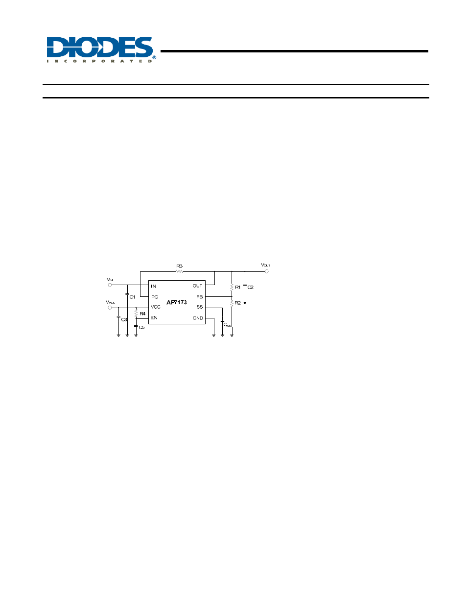
Figure 30. Delayed Start Using an RC
Circuit to Enable AP7173
POWER-GOOD
The power-good (PG) pin is an open-drain output and can
be pulled up through a resistor of 10k
Ω to1MΩ to V
IN
, V
OUT
or any other rail that is 5.5V or lower. When the V
OUT
≥
V
PG,TH
+V
PG,HYS
, the PG output is high-impedance; if the
V
OUT
drops to below V
PG,TH
, V
VCC
≤ 1.9V or the device is
disabled, the PG pin is pulled to low by an internal
MOSFET.
OVER-CURRENT AND SHORT-CIRCUIT
PROTECTION
The AP7173 features a factory-trimmed, temperature and
supply voltage compensated internal current limit and an
over-current protection circuitry to protect the device
against overload conditions. It limits the device current to
a typical value of 3A and reduces the V
OUT
when the load
tries to pull more current.
For more effective protection against short-circuit failure,
the AP7173 also includes a short-circuit foldback
mechanism that lowers the current limit to a typical value
of 1.0A when the V
FB
drops to below 0.2V.
THERMAL PROTECTION
Thermal shutdown limits the AP7173 junction
temperature and protects the device from damage as a
result of overheating.
Thermal protection turns off the V
OUT
when the AP7173’s
junction temperature rises to approximately +150
°C,
allowing it to cool down. When the junction temperature
drops to approximately +130
°C, the output is re-enabled.
Therefore, the thermal protection circuit may cycle on
and off at a rate dependent on the power dissipation,
thermal resistance, and ambient temperature.
POWER DISSIPATION
Thermal shutdown is intented to protect the AP7173
against abnormal overheating. For normal operation,
excessive power dissipation should be avoided and good
heatsinking should be provided. Power dissipation in the
device is the product of the device dropout voltage and
the load current,
P
D
= (V
IN
- V
OUT
) x I
OUT
As can be seen, power dissipation can be minimized by
using the lowest input voltage necessary to achieve the
required output voltage regulation.
To ensure that the device junction temperature does not
exceed the specified limit of 125
°C, an application should
provide heat conduction paths that have junction-to-
ambient thermal resistance lower than the calculated
value here:
R
θJA
= (125°C –T
A
) / P
D
For the DFN package with exposed pad, the primary
conduction path for heat is through the exposed pad to
the printed circuit board (PCB). The pad should be
attached to an appropriate amount of copper PCB area to
ensure that the device does not overheat.