Application information – Diodes AP65550 User Manual
Page 11
AP65550
Document number: DS36336 Rev. 2 - 2
11 of 14
www.diodes.com
April 2014
© Diodes Incorporated
AP65550
Application Information
(cont.)
Inductor
Calculating the inductor value is a critical factor in designing a buck converter. For most designs, the following equation can be used to calculate
the inductor value;
SW
L
IN
OUT
IN
OUT
f
ΔI
V
)
V
(V
V
L
Where
L
ΔI
is the inductor ripple current.
And
SW
f
is the buck converter switching frequency.
Choose the inductor ripple current to be 30% of the maximum load current. The maximum inductor peak current is calculated from:
2
ΔI
I
I
L
LOAD
L(MAX)
Peak current determines the required saturation current rating, which influences the size of the inductor. Saturating the inductor decreases the
converter efficiency while increasing the temperatures of the inductor and the internal MOSFETs. Hence choosing an inductor with appropriate
saturation current rating is important.
A 1µH to 3.3µH inductor with a DC current rating of at least 25% percent higher than the maximum load current is recommended for most
applications. For highest efficiency, the inductor’s DC resistance should be less than 100mΩ. Use a larger inductance for improved efficiency
under light load conditions.
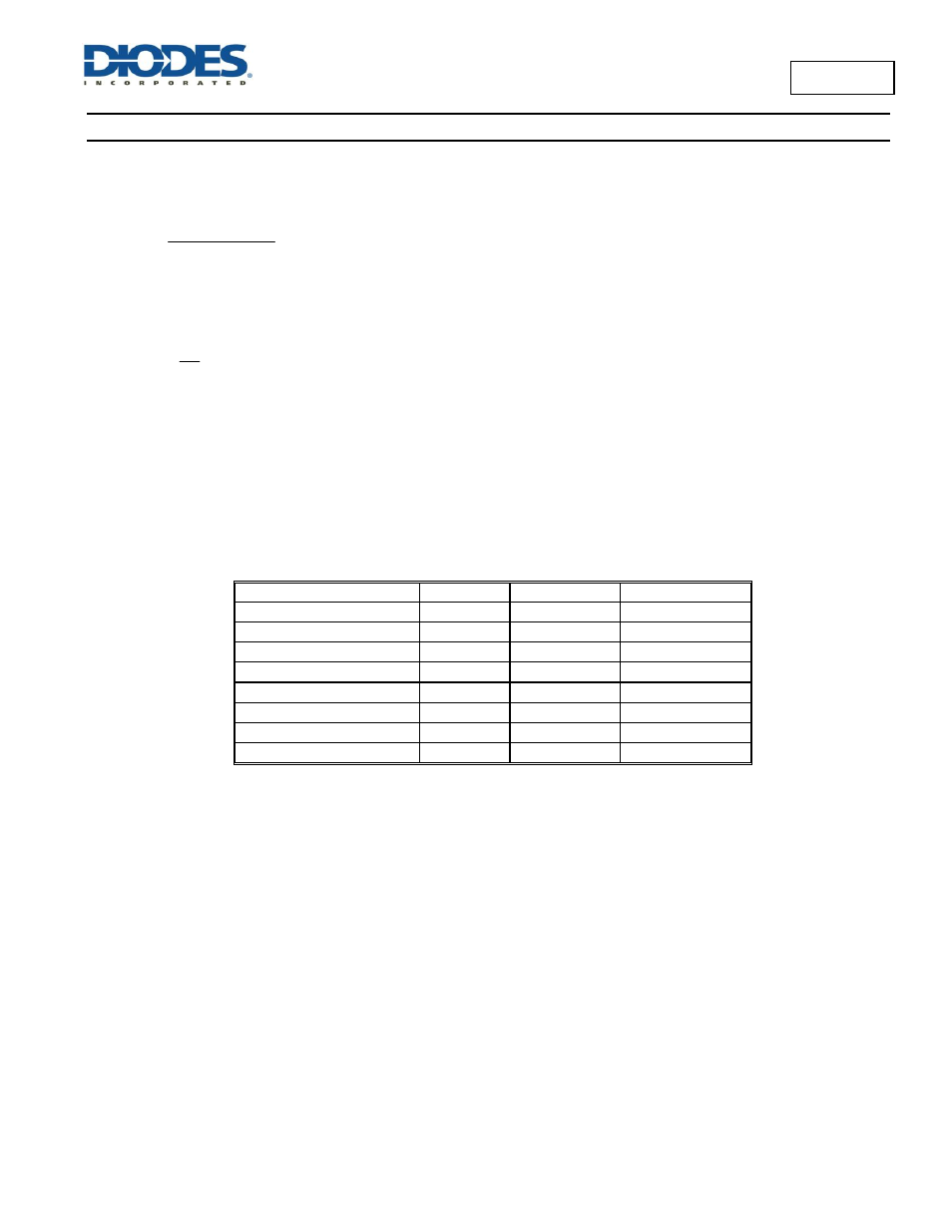
The phase boost can be achieved by adding a additional feed forward capacitor (C4) in parallel with R1.
Output Voltage (V)
C10(pF)
L1(µH)
C5+C9(µF)
1
—
1.0-1.5
22-68
1.05
—
1.0-1.5
22-68
1.2
—
1.0-1.5
22-68
1.5
—
1.5
22-68
1.8
5-22
1.5
22-68
2.5
5-22
2.2
22-68
3.3
5-22
2.2
22-68
5
5-22
3.3
22-68
Table 2. Recommended Component Selection
Input Capacitor
The input capacitor reduces the surge current drawn from the input supply and the switching noise from the device. The input capacitor has to
sustain the ripple current produced during the on time on the upper MOSFET. It must hence have a low ESR to minimize the losses.
The RMS current rating of the input capacitor is a critical parameter that must be higher than the RMS input current. As a rule of thumb, select an
input capacitor which has RMs rating that is greater than half of the maximum load current.
Due to large dI/dt through the input capacitors, electrolytic or ceramics should be used. If a tantalum must be used, it must be surge protected.
Otherwise, capacitor failure could occur. For most applications, greater than 10µF ceramic capacitor is sufficient.
Output Capacitor
The output capacitor keeps the output voltage ripple small, ensures feedback loop stability and reduces the overshoot of the output voltage. The
output capacitor is a basic component for the fast response of the power supply. In fact, during load transient, for the first few microseconds it
supplies the current to the load. The converter recognizes the load transient and sets the duty cycle to maximum, but the current slope is limited
by the inductor value.