Zxld1371, Applications information – Diodes ZXLD1371 User Manual
Page 25
ZXLD1371
ZXLD1371
Document number: DS35436 Rev. 1 - 2
25 of 42
February 2012
© Diodes Incorporated
A Product Line of
Diodes Incorporated
Applications Information
(cont.)
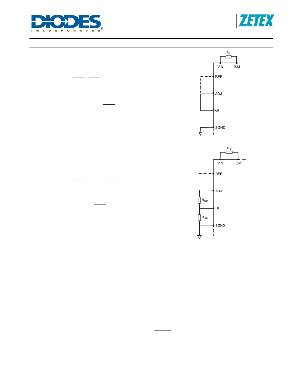
Buck topology
In Buck mode, GI is connected to ADJ as in Figure 5. The LED
current depends only upon R
S
, V
ADJ
and V
REF
. From Equation 1
above,
⎟⎟
⎠
⎞
⎜⎜
⎝
⎛
⎟⎟
⎠
⎞
⎜⎜
⎝
⎛
=
V
V
I
218
.
0
R
REF
ADJ
LED
SBUCK
Equation 10
If ADJ is directly connected to VREF, this becomes:
⎟⎟
⎠
⎞
⎜⎜
⎝
⎛
=
I
218
.
0
R
LED
SBUCK
Figure 5. Setting LED Current in Buck
Configuration
Boost and Buck-boost topology
For Boost and Buck-boost topologies, the LED current depends
upon the resistors, R
S
, R
GI1
, and R
GI2
as in Equations 4 and 2
above. There is more than one degree of freedom. That is to say,
there is not a unique solution. From Equation 4,
⎟⎟
⎠
⎞
⎜⎜
⎝
⎛
=
I
225
.
0
R
LED
SBoostBB
⎟⎟
⎠
⎞
⎜⎜
⎝
⎛
V
V
ADJ
_
GI
REF
ADJ
Equation 11
If ADJ is connected to REF, this becomes
⎟⎟
⎠
⎞
⎜⎜
⎝
⎛
=
I
225
.
0
R
LED
SBoostBB
ADJ
_
GI
GI_ADJ is given by Equation 2, repeated here for convenience:
⎟
⎠
⎞
⎜
⎝
⎛
+
=
2
RGI
1
RGI
1
RGI
ADJ
_
GI
Figure 6. Setting LED current in Boost and
Buck-boost configurations
Note that from considerations of ZXLD1371 input bias current, the recommended limits for R
GI1
are:
22k
Ω < R
GI1
< 100k
Ω Equation 12
The additional degree of freedom allows us to select GI_ADJ within limits but this may affect overall performance a little.
As mentioned above, the working voltage range at the GI pin is restricted. The permitted range of GI_ADJ in Boost or
Buck-boost configuration is
0.2 < GI_ADJ < 0.5 Equation 13
The mean voltage across the sense resistor is
V
RS
= I
COIL
R
S
Equation 14
Note that if GI_ADJ is made larger, these equations show that R
S
is increased and V
RS
is increased. Therefore, for the
same coil current, the dissipation in R
S
is increased. So, in some cases, it is better to minimize GI_ADJ. However,
consider Equation 5. If ADJ is connected to REF, this becomes
225
.
0
V
RS
=
⎟
⎠
⎞
⎜
⎝
⎛
− D
1
ADJ
_
GI
This shows that V
RS
becomes smaller than 225mV if GI_ADJ < 1 - D. If also D is small, V
RS
can become too small. For
example if D = 0.2, and GI_ADJ is the minimum value of 0.2, then V
RS
becomes 0.225* 0.2 / 0.8 = 56.25 mV. This will
increase the LED current error due to small offsets in the system, such as mV drop in the copper printed wiring circuit, or
offset uncertainty in the ZXLD1371. If now, GI_ADJ is increased to 0.4 or 0.5, V
RS
is increased to a value greater than
100mV.