3 motherboard layout, 10 chapter 1: product introduction, Mcp7a-s – Asus P5N7A-VM User Manual
Page 22
1-10
Chapter 1: Product Introduction
1.5.3
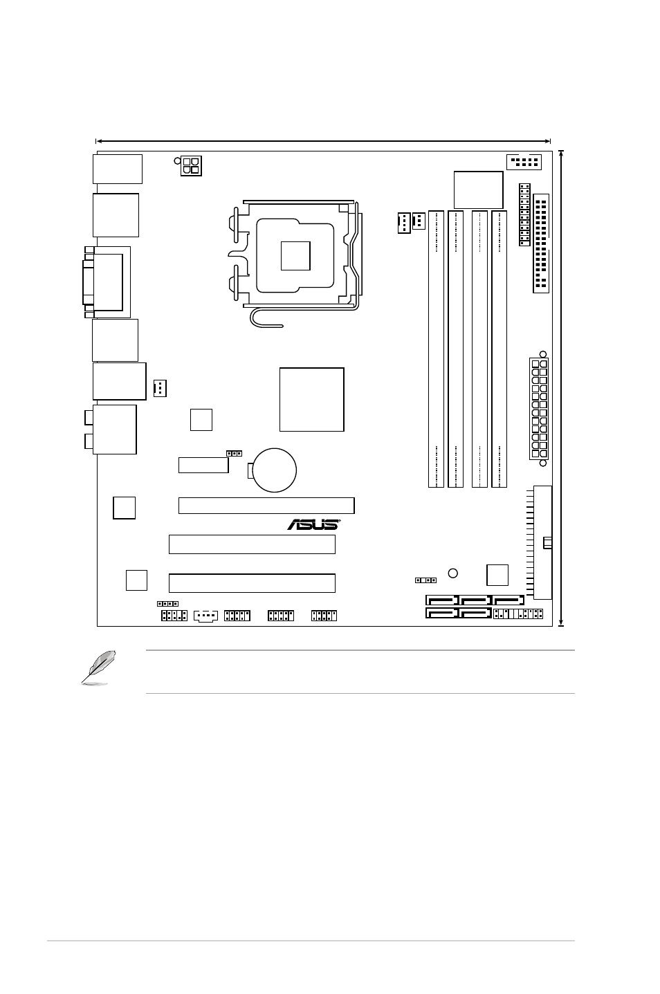
Motherboard layout
Refer to 1.10 Connectors for more information about rear panel connectors
and internal connectors.
P5N7A-VM
23.4cm (9.2in)
SATA4
SATA1
SATA5
SATA6
SATA2
PWR_FAN
CHA_FAN
USB78
USB910
USB1112
AAFP
MCP7A-S
DDR2 DIMM_B1 (64 bit,240-pin module
)
DDR2 DIMM_B2 (64 bit,240-pin module
)
DDR2 DIMM_A1 (64 bit,240-pin module
)
DDR2 DIMM_A2 (64 bit,240-pin module
)
CR2032 3V
Lithium Cell
CMOS Power
PCI2
PCI1
PCIEX16
PCIEX1_1
CD
CHASSIS
ATX12V
FL
O
PP
Y
Super I/O
CPU_FAN
SB_PWR
CLRTC
SPDIF_OUT
RTL
8211CL
LGA775
PRI_IDE
8Mb
BIOS
LPT
KB/MS_USB56
VG
A_
DV
I
SPDIFO_
HDMI_
DP_
F_
ESATA_
USB34
LAN1_USB12
AUDIO
COM1
PANEL
ALC1200
JMB
368
24.4cm (9.6in)
EA
TXPW
R
See also other documents in the category Asus Motherboard:
- P5B (56 pages)
- P5B Premium Vista Edition (188 pages)
- P5B (140 pages)
- P5KPL-VM/1394/SI (94 pages)
- M2N68-CM (28 pages)
- P5AD2 Premium (8 pages)
- P5GD1-VM (92 pages)
- P5AD2-E Premium (2 pages)
- P5GD1-VM (88 pages)
- DELUXE A7N8X-E (114 pages)
- P5KPL-AM SE (40 pages)
- P5KPL-AM SE (38 pages)
- P5KPL-AM SE (62 pages)
- P4S8X-X (64 pages)
- P5K-VM (98 pages)
- K8V-X SE (82 pages)
- M2N68-AM SE2 (40 pages)
- P4P800 SE (125 pages)
- P4P800 SE (16 pages)
- DELUXE SERIES M3A32-MVP (176 pages)
- P5AD2 Deluxe (148 pages)
- M4A79 Deluxe (122 pages)
- A7V266-E (108 pages)
- Application Manual (9 pages)
- Application Manual (3 pages)
- Application Manual (1 page)
- Application Manual (5 pages)
- Application Manual (11 pages)
- Application Manual (10 pages)
- Application Manual (4 pages)
- Application Manual (8 pages)
- Application Manual (2 pages)
- Application Manual (6 pages)
- M4A88T-I DELUXE (70 pages)
- M4A88T-I DELUXE (44 pages)
- P9X79 (156 pages)
- P9X79 DELUXE (2 pages)
- RAMPAGE IV GENE (1 page)
- P8H61-M PLUS V3 (64 pages)
- A85XM-A (78 pages)
- M4A78L-M LE (64 pages)
- M2N68-AM (38 pages)
- M2N68-AM (96 pages)
- M2N68-AM (62 pages)
- Blitz Extreme (188 pages)