Asus AP120-E1 User Manual
Page 41
3-3
ASUS AP120-E1 user guide
2
3
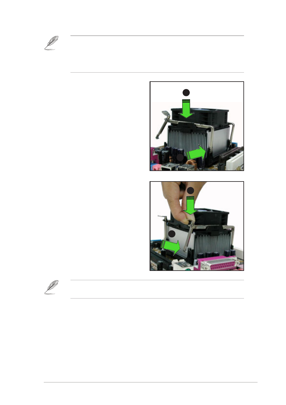
2. Align the retention bracket with
the rails on the side of the CPU
fan.
3. Attach the retention bracket hook
into the retention module hole.
•
The retention module base is already installed on the motherboard
upon purchase.
•
Do not remove the retention module base when installing the CPU
or installing other system components.
4. Carefully press down the locking
lever on the other side of the
retention bracket.
5. Attach the locking lever hook into
the retention module hole to
secure the fan and heatsink
assembly in place.
6. Follow steps 2 to 5 to re-install
the second retention bracket.
4
5
The illustrations are for reference only and may not exactly match the
actual component.
See also other documents in the category Asus Computer hardware:
- AP2500 (40 pages)
- AP1700-S5 (58 pages)
- RS700-E6/ERS4 (138 pages)
- AP1600R-E2(AA2) (150 pages)
- P7F-E (162 pages)
- RS161-E4/PA2 (126 pages)
- RS163-E4/RX4 (11 pages)
- M2N-LR (113 pages)
- P5BV/SAS (184 pages)
- K8N-DRE (142 pages)
- RS161-E5/PA2 (124 pages)
- LSI SAS3442X-R (68 pages)
- PIKE 2208 (16 pages)
- ESC4000/FDR G2 (200 pages)
- ESC4000 (162 pages)
- ESC4000 (22 pages)
- PSCH-SR/IDE (102 pages)
- P9D-M (156 pages)
- RS740-E7-RS24-EG (212 pages)
- P5M2-E/4L (12 pages)
- ESC2000 G2 (226 pages)
- TS700-E6/RS8 (166 pages)
- RS160-E3/PS4 (140 pages)
- PU-DLS (134 pages)
- TR-DLSR (100 pages)
- P5BV-C/2L (161 pages)
- TS100-E5/PI4 (166 pages)
- ESC1000 Personal SuperComputer (184 pages)
- NRL-LS (120 pages)
- PCI-DA2200 (369 pages)
- P8C WS (140 pages)
- RS120-E4/PA4 (174 pages)
- P5MT-M (150 pages)
- TS Mini (112 pages)
- TS Mini (114 pages)
- TS Mini (2 pages)
- P5MT-MX/C (156 pages)
- AP140R-E1 (52 pages)
- AP140R-E1 (132 pages)
- ASMB6-iKVM (114 pages)
- DSBF-D16/SAS (200 pages)
- DSBF-D16 (202 pages)
- RS160-E5 (164 pages)
- Z8PE-D12X (170 pages)
- Z8PE-D12X (168 pages)