Electrical specifications (continued) – GE Industrial Solutions NQR002A0X4 User Manual
Page 3
Preliminary Data Sheet
February 28, 2012
NQR002A0X4: Non-Isolated DC-DC Power Modules
3 – 14Vdc input; 0.6Vdc to 5.5Vdc Output; 2A output current
LINEAGE
POWER
3
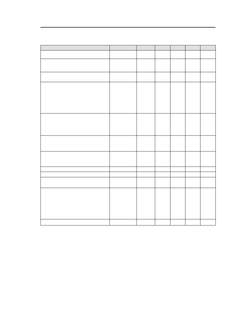
Electrical Specifications
(continued)
Parameter
Device
Symbol
Min
Typ
Max
Unit
Output Voltage Set-point (with 0.5% tolerance
for external resistor used to set output voltage)
All
V
O, set
-1.5 +1.5
%
V
O, set
Output Voltage
All
V
O, set
-3.0
⎯
+3.0 %
V
O, set
(Over all operating input voltage, resistive load,
and temperature conditions until end of life)
Adjustment Range
All
V
O
0.6 5.5
Vdc
Selected by an external resistor
Output Regulation (for V
o
≥ 2.5Vdc)
Line (V
IN
=V
IN, min
to V
IN, max
) All
-0.4
⎯
+0.4 %
V
O, set
Load (I
O
=I
O, min
to I
O, max
) All
⎯
0.8 %
V
O, set
Output Regulation (for V
o
<2.5Vdc)
Line (V
IN
=V
IN, min
to V
IN, max
) All
-10
⎯
+10 mV
Load (I
O
=I
O, min
to I
O, max
) All
⎯
20 mV
Output Ripple and Noise on nominal output
(V
IN
=V
IN, nom
and I
O
=I
O, min
to I
O, max
Cout = 22μF)
Peak-to-Peak (5Hz to 20MHz bandwidth)
All
⎯
50 100
mV
pk-pk
RMS (5Hz to 20MHz bandwidth)
All
⎯
20 38
mV
rms
External Capacitance
1
Without the Tunable Loop
TM
ESR ≥ 1 mΩ All
C
O, max
22
⎯
47
μF
With the Tunable Loop
TM
ESR ≥ 0.15 mΩ All
C
O, max
0
⎯
1000
μF
ESR ≥ 10 mΩ All
C
O, max
0
⎯
3000
μF
Output Current
All
I
o
0 2
Adc
Output Current Limit Inception (Hiccup Mode )
All
I
O, lim
180
%
I
o,max
Output Short-Circuit Current
All
I
O, s/c
140 Arms
(V
O
≤250mV) ( Hiccup Mode )
Efficiency (V
IN
= 6Vdc)
V
O,set
= 0.6Vdc
η
69.2
%
V
IN
= 12Vdc, T
A
=25°C V
O, set
= 1.2Vdc
η
80.4
%
I
O
=I
O, max ,
V
O
= V
O,set
V
O,set
= 1.8Vdc
η
85.5
%
V
O,set
= 2.5Vdc
η
88.9
%
V
O,set
= 3.3Vdc
η
91
%
V
O,set
= 5.0Vdc
η
93.3
%
Switching Frequency
All
f
sw
⎯
600
⎯
kHz
1
External capacitors may require using the new Tunable Loop feature to ensure that the module is stable as well as
getting the best transient response. See the Tunable Loop
TM
section for details.