GE Industrial Solutions AKD-8 User Manual
Page 5
(Using Accepted Normal Values of System
Capacitance Charging Current)
High Resistance Pulsing Ground Detector
480 Volt WYE
1. Familiarize yourself with this instruction and with the
grounding circuit.
2. Adjust the neutral ground resistance by moving jumpers
on resistor terminal board such that the ground current
with one ground fault is greater than the System
Capacitance Charging Current (I
c
)
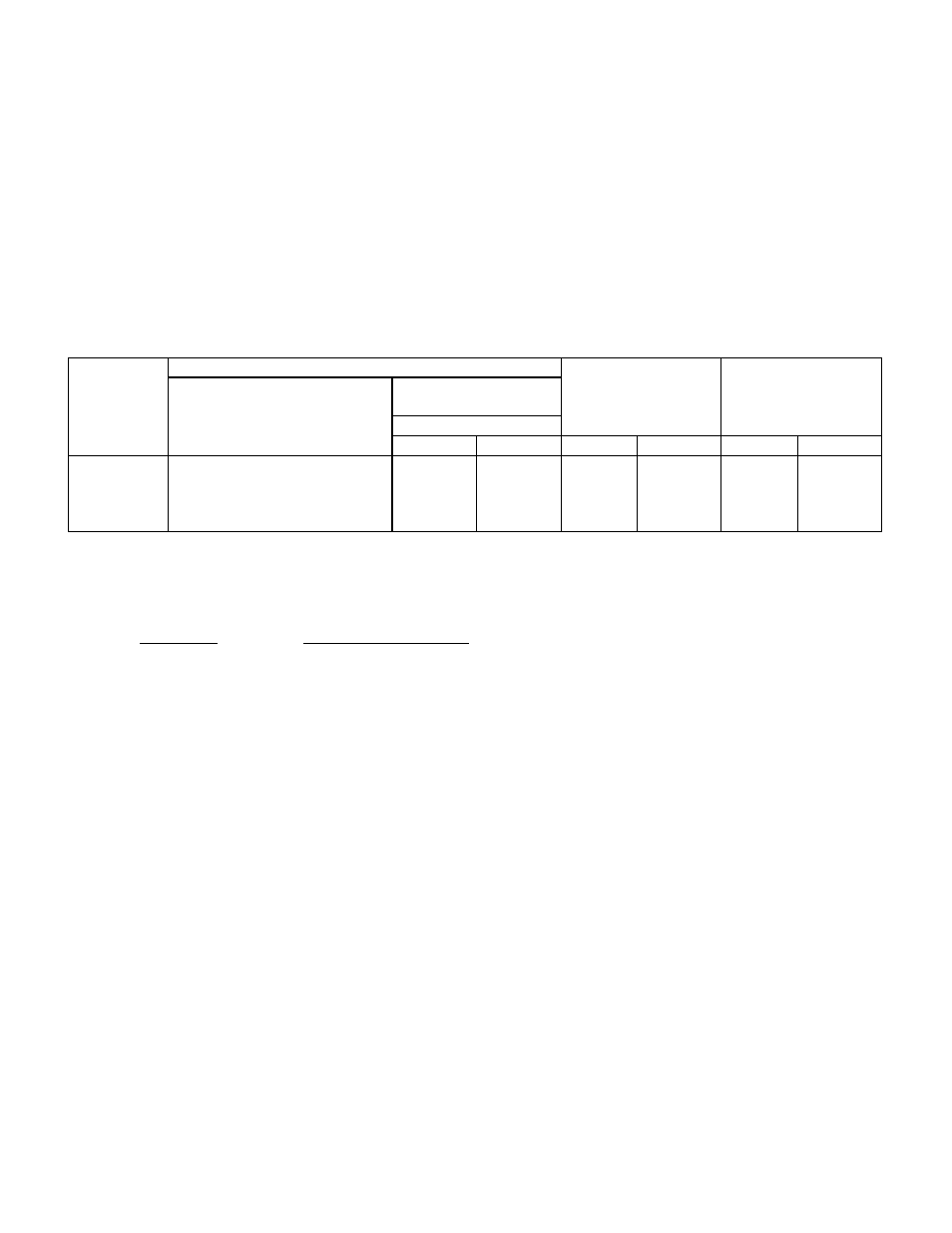
TABLE 5.1
Neutral Ground Resistor Data
I
c
-
Maximum
Jumper Connection
Ground Fault
Pulsing
Primary
On Resistor Terminal Board
Resistance (OHMS)
Data
Data
(See Note 2)
Normal
Pulsing
Amps
Watts
Amps
Watts
0.8
1.1
2.3
3.5
3-4
1-2, 3-4
1-2, 3-5, 4-6
1-3, 2-5, 4-6
304
228
114
76
76
76
38
38
0.91
1.21
2.43
3.65
252
334
672
1010
3.65
3.65
7.3
7.3
556
605
1213
1417
3.
Maximum normal expected ground fault for system
kVA: kVA shown:
TOTAL SYSTEM
MAX NORMAL
SIZE (kVA)
GROUND FAULT AMPS
1000
0.9
1500
1.2
2000
2.4
3000
3.6
4. Set the meter relay (MR) such that the high-set pointer,
"RED" is the maximum setting and the low-set pointer,
"BLUE" is just higher than the voltage across the neutral
ground resistor due to the system capacitance charging
current.
NOTE: 1. The control voltage must be within 107-127
Volts, otherwise meter relay will not operate.
2. Refer to ground system elementary for resistor
terminal board. Never short out resistors by
connecting terminal 5 to 4 or 6.
5