6 complete parallel system shutdown, Complete parallel system shutdown – GE Industrial Solutions SG Series 750 T12 UL S2 User Manual User Manual
Page 63
Modifications reserved
Page 63/71
OPM_SGS_USM_M75_M75_2US_V010.doc
User Manual SG Series 750 UL S2 & SG Series 750 T12 UL S2
7.2.6 Complete Parallel System shutdown
NOTE !
Follow this procedure only in case the UPS Parallel System and the Load must be
completely powered-down.
If eBoost™ option is available, make sure that eBoost™ Operation Mode is disabled
before starting the shutdown procedure.
Initial situation:
The Load is powered by SG Series 750 or SG Series 750 T12 Parallel System supplying
the Parallel Bus.
With the UPS Parallel System in normal operation and the Inverters supplying the Load, the UPS Output
Switches Q1, Input Circuit Breakers CB4 and Battery Circuit Breakers are closed (Pos. I) and the
External Maintenance Bypass Switches (option) are open (Pos. O).
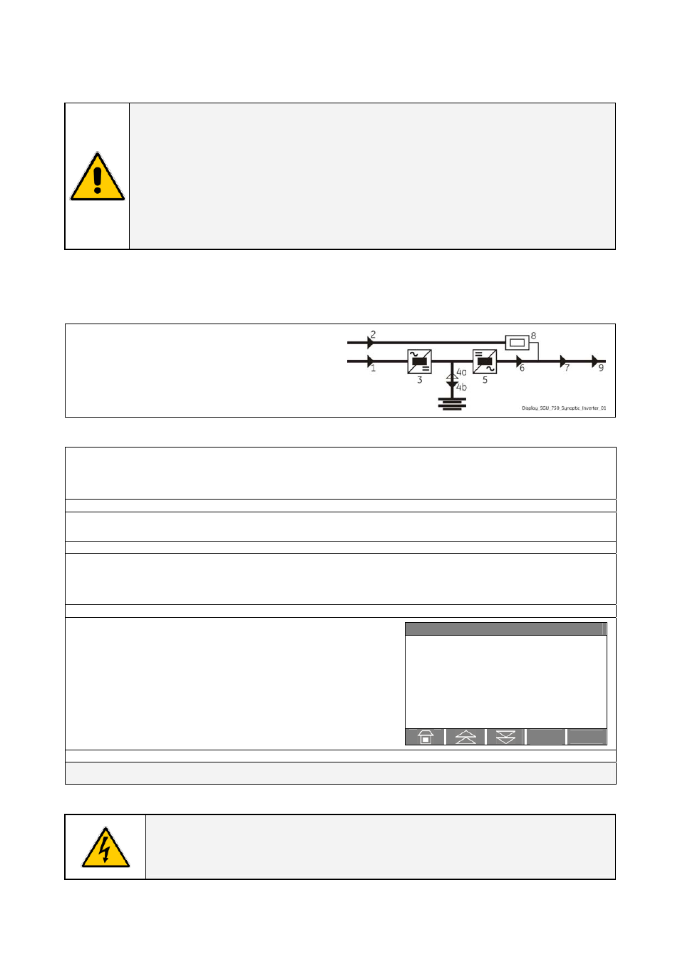
Initial status:
Load supplied from all Inverters of the Parallel
System.
The Synoptic Diagram, on all UPS units, must
display the status “load supplied by inverter”.
1. Press “Load Off” key on anyone of the Parallel Units
All the contactors are opened in all units dropping the load. Inverter and rectifier on all units is shut down.
Only DC bus may stay on due to battery (only for UPS configuration without external Battery Breaker).
2. Open the UPS Output Switch Q1 (Pos. O) on all Units.
3. Disconnect the Battery from all Units (only for UPS configuration without external Battery
Breaker).
Wait a minimum of 5 minutes for DC-Link Capacitors to discharge.
`
Home\Meter
BATTERY
V
15 V
I
5.0 A
T
+25° C
Charge level
80 %
Autonomy
12 Min
4. Disconnect the Utility, on all UPS units, from the
input distribution only when the DC-Link voltage
results to be below 15Vdc.
All the LEDs and the LCD display on the panels must be OFF.
END OF PROCEDURE
DANGER !
It will take 5 minutes for the DC capacitors to discharge.
Open only the front door, do not open any other part of the UPS.