Data sheet, Thermal considerations (continued) – GE Industrial Solutions JRW450U Orca Series User Manual
Page 10
GE
Data Sheet
JRCW450U Orca Series; DC-DC Converter Power Modules
36–75 Vdc Input; 48.0Vdc Output; 450W Output
June 7, 2013
©2012 General Electric Company. All rights reserved.
Page 10
Thermal Considerations (continued)
For reliable operation with Vin=48V this temperature should
no texceed 100ºC at either T
REF 1
or T
REF 2
, or 130 ºC at T
REF3
for
applications using forced convection airflow without heat
sink, or in cold plate applications. The temperatures at either
T
REF 1
or T
REF 2
should not exceed 90ºC, when using a 1in. heat
sink in forced convection airflow. The output power of the
module should not exceed the rated power for the module as
listed in the ordering Information table. Although the
maximum T
REF
temperature of the power modules is
discussed above, you can limit this temperature to a lower
value for extremely high reliability.
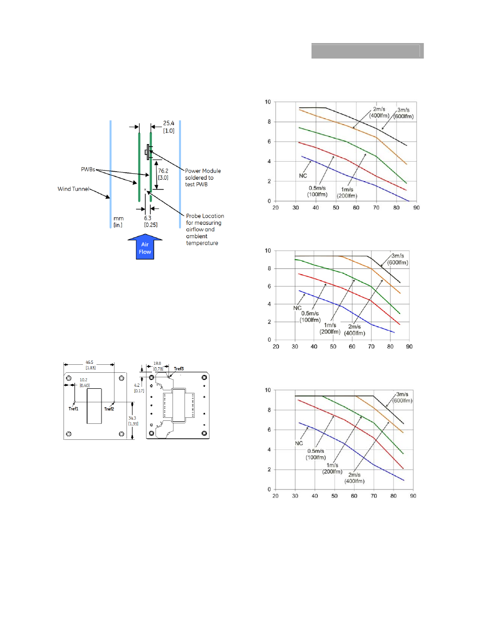
Figure 16.
Case (T
REF
) Temperature Measurement Location
(top view).
Thermal Derating
Thermal derating is presented for different applications in
Figure 17, 18 and 19. The JRCW450U module is mounted in a
traditional open chassis or cards with forced air flow. The
module is cooled by heat removal into a forced airflow that
passes through the interior of the module and over the top
base plate and/or attached heat sink. Conduction cooled
thermal derating is presented in Figure 20.
Out
put Cur
rent, I
O
(A)
Ambient Temperature, T
A
(
o
C)
Figure 17. Derating Output Current vs. local Ambient
temperature and Airflow, No Heat sink, Vin=48V, airflow
from Vi(-) to Vi(+).
O
utput Cur
rent, I
O
(A)
Ambient Temperature, T
A
(
o
C)
Figure 18. Derating Output Current vs. local Ambient
temperature and Airflow, 0.5” Heat sink, Vin=48V, airflow
from Vi(-) to Vi(+).
Output C
urrent,
I
O
(A
)
Ambient Temperature, T
A
(
o
C)
Figure 19. Derating Output Current vs. local Ambient
temperature and Airflow, 1.0” Heat sink, Vin=48V, airflow
from Vi(-) to Vi(+).