Thermal considerations, Emc considerations, Layout considerations – GE Industrial Solutions KNW015A0F (Sixteenth-Brick) User Manual
Page 9
Data Sheet
February 28, 2011
KNW015A0F Series Power Modules:
36 – 75Vdc Input; 3.3Vdc Output; 15A Output Current
LINEAGE
POWER
9
Thermal Considerations
(continued)
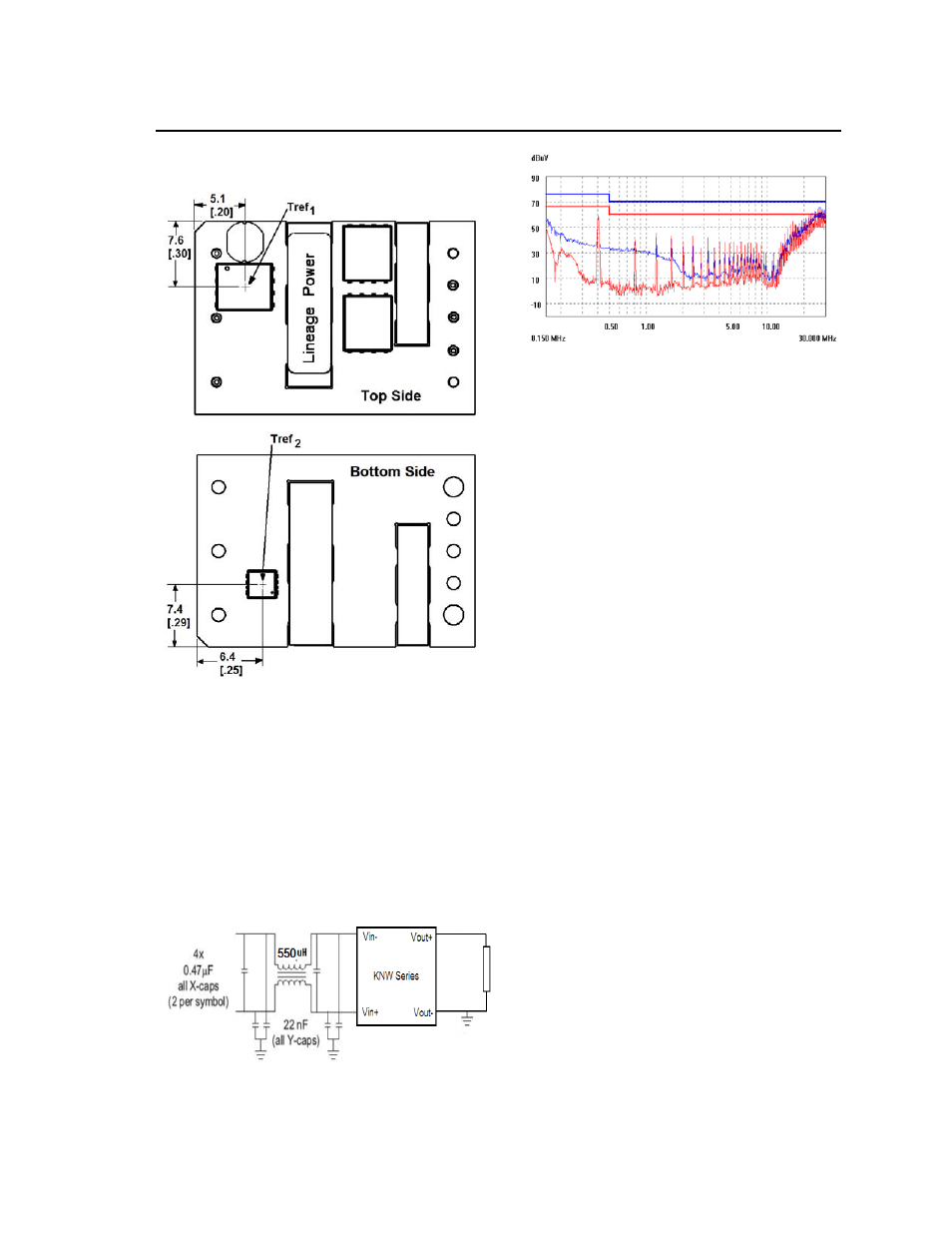
Figure 13. Tref
x
Temperature Measurement
Location.
Please refer to the Application Note “Thermal
Characterization Process For Open-Frame Board-
Mounted Power Modules” for a detailed discussion of
thermal aspects including maximum device
temperatures.
EMC Considerations
The KNW015A0F series module shall also meet limits
of EN55022 Class A with a recommended single
stage filter, shown in Figure 14. Please contact your
Lineage Power Sales Representative for further
information.
Figure 14. Single stage filter used for test results.
Figure 15. KNW015A0F Quasi Peak Conducted
Emissions with EN 55022 Class A limits, Figure 14
filter (V
IN
= V
IN,NOM
, I
o
= 0.80 I
o,max
).
Layout Considerations
Avoid placing copper areas on the outer layer of the
application PCB directly underneath the power
module in the keep out areas shown in the
Recommended Pad Layout figures. Also avoid
placing via interconnects underneath the power
module in these keep out areas.