12a digital slimlynx, Non-isolated dc-dc power modules, Preliminary data sheet – GE Industrial Solutions 12A Digital SlimLynx User Manual
Page 13: Design considerations, Safety considerations
GE
Preliminary Data Sheet
12A Digital SlimLynx
TM
: Non-Isolated DC-DC Power Modules
3Vdc –14.4Vdc input; 0.45Vdc to 5.5Vdc output; 12A Output Current
February 19, 2014
©2014 General Electric Company. All rights reserved.
Page 13
Design Considerations
Input Filtering
The 12A Digital SlimLynx
TM
module should be connected to
a low ac-impedance source. A highly inductive source can
affect the stability of the module. An input capacitance
must be placed directly adjacent to the input pin of the
module, to minimize input ripple voltage and ensure
module stability.
To minimize input voltage ripple, ceramic capacitors are
recommended at the input of the module. Figure 37 shows
the input ripple voltage for various output voltages at 12A
of load current with 2x22 µF or 3x22 µF ceramic
capacitors and an input of 12V.
Figure 37. Input ripple voltage for various output
voltages with 2x22 µF or 3x22 µF ceramic capacitors at
the input (12A load). Input voltage is 12V.
Output Filtering
These modules are designed for low output ripple voltage
and will meet the maximum output ripple specification with
3x0.047 µF ceramic and 2x47 µF ceramic capacitors at the
output of the module. However, additional output filtering
may be required by the system designer for a number of
reasons. First, there may be a need to further reduce the
output ripple and noise of the module. Second, the dynamic
response characteristics may need to be customized to a
particular load step change.
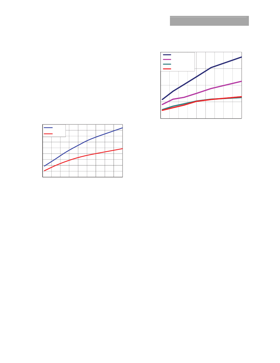
To reduce the output ripple and improve the dynamic
response to a step load change, additional capacitance at
the output can be used. Low ESR polymer and ceramic
capacitors are recommended to improve the dynamic
response of the module. Figure 38 provides output ripple
information, measured with a scope with its Bandwidth
limited to 20MHz for different external capacitance values at
various Vo and a full load current of 12A. For stable
operation of the module, limit the capacitance to less than
the maximum output capacitance as specified in the
electrical specification table. Optimal performance of the
module can be achieved by using the Tunable Loop
TM
feature
described later in this data sheet.
Figure 38. Output ripple voltage for various output
voltages with external 2x47 µF, 4x47 µF, 6x47 µF or 8x47
µF ceramic capacitors at the output (12A load). Input
voltage is 12V.
Safety Considerations
For safety agency approval the power module must be
installed in compliance with the spacing and separation
requirements of the end-use safety agency standards, i.e.,
UL 60950-1 2nd, CSA C22.2 No. 60950-1-07, DIN EN 60950-
1:2006 + A11 (VDE0805 Teil 1 + A11):2009-11; EN 60950-
1:2006 + A11:2009-03.
For the converter output to be considered meeting the
requirements of safety extra-low voltage (SELV), the input
must meet SELV requirements. The power module has
extra-low voltage (ELV) outputs when all inputs are ELV.
The input to these units is to be provided with a fast acting
fuse (e.g. ABC Bussmann) with a maximum rating of 20 A in
the positive input lead
.
0
50
100
150
200
250
300
350
400
450
0.5
1
1.5
2
2.5
3
3.5
4
4.5
5
1x22uF
2x22 uF
0
10
20
30
40
0.5
1
1.5
2
2.5
3
3.5
4
4.5
5
R
ipple
(m
V
p
-p)
Output Voltage(Volts)
2x47uF Ext Cap
4x47uF Ext Cap
6x47uF Ext Cap
8x47uF Ext Cap