6a analog picodlynx, Non-isolated dc-dc power modules, Preliminary data sheet – GE Industrial Solutions 6A Analog PicoDLynx User Manual
Page 14: Ω − = k vo rtrim 6 . 0 12, Module
GE
Preliminary Data Sheet
6A Analog PicoDLynx
TM
: Non-Isolated DC-DC Power Modules
3Vdc –14.4Vdc input; 0.6Vdc to 5.5Vdc output; 6A Output Current
December 7, 2012
©2012 General Electric Company. All rights reserved.
Page 14
(
)
Ω
−
=
k
Vo
Rtrim
6
.
0
12
Rtrim is the external resistor in kΩ
Vo is the desired output voltage.
Table 1
V
O, set
(V)
Rtrim (KΩ)
0.6 Open
0.9 40
1.0 30
1.2 20
1.5 13.33
1.8 10
2.5 6.316
3.3 4.444
5.0 2.727
Remote Sense
The power module has a Remote Sense feature to minimize the
effects of distribution losses by regulating the voltage at the
SENSE pin. The voltage between the SENSE pin and VOUT pin
should not exceed 0.5V.
Voltage Margining
Output voltage margining can be implemented in the module
by connecting a resistor, R
margin-up
, from the Trim pin to the
ground pin for margining-up the output voltage and by
connecting a resistor, R
margin-down
, from the Trim pin to output
pin for margining-down. Figure 43 shows the circuit
configuration for output voltage margining. The POL
Programming Tool, available at
www.lineagepower.com
under
the Downloads section, also calculates the values of R
margin-up
and R
margin-down
for a specific output voltage and % margin.
Please consult your local GE technical representative for
additional details.
Figure 43. Circuit Configuration for margining Output
voltage.
Overcurrent Protection
To provide protection in a fault (output overload)
condition, the unit is equipped with internal
current-limiting circuitry and can endure current limiting
continuously. At the point of current-limit inception, the
unit enters hiccup mode. The unit operates normally
once the output current is brought back into its specified
range.
Overtemperature Protection
To provide protection in a fault condition, the unit is
equipped with a thermal shutdown circuit. The unit will
shutdown if the overtemperature threshold of TBD
o
C(typ)
is exceeded at the thermal reference point T
ref
. Once the
unit goes into thermal shutdown it will then wait to cool
before attempting to restart.
Input Undervoltage Lockout
At input voltages below the input undervoltage lockout
limit, the module operation is disabled. The module will
begin to operate at an input voltage above the
undervoltage lockout turn-on threshold.
Power Good
The module provides a Power Good (PGOOD) signal that
is implemented with an open-drain output to indicate
that the output voltage is within the regulation limits of
the power module. The PGOOD signal will be de-asserted
to a low state if any condition such as overtemperature,
overcurrent or loss of regulation occurs that would result
in the output voltage going ±10% outside the setpoint
value. The PGOOD terminal can be connected through a
pullup resistor (suggested value 100K
Ω) to a source of
5VDC or lower.
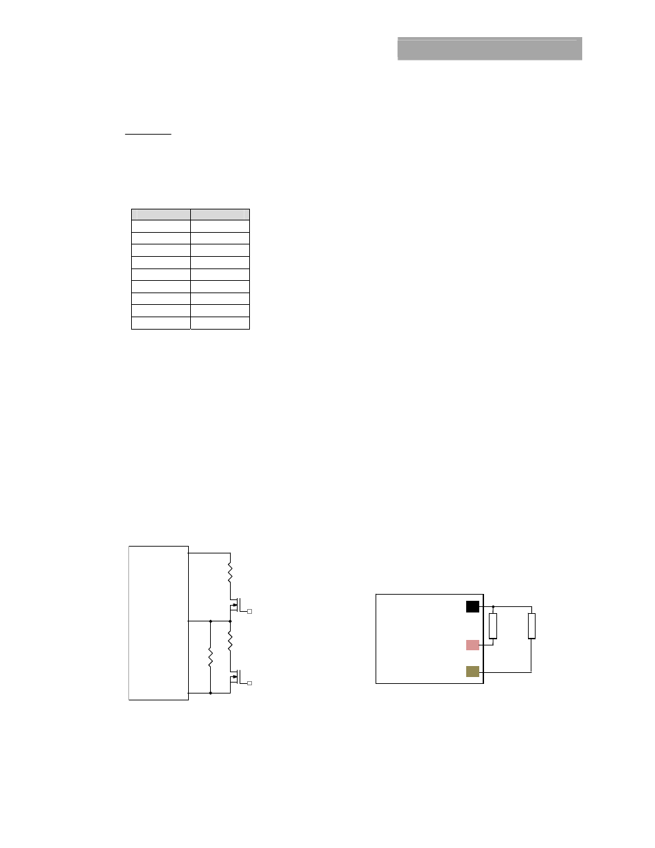
Dual Layout
Identical dimensions and pin layout of Analog and Digital
PicoDLynx modules permit migration from one to the
other without needing to change the layout. To support
this, 2 separate Trim Resistor locations have to be
provided in the layout. For the digital modules, the
resistor is connected between the TRIM pad and SGND
and in the case of the analog module it is connected
between TRIM and GND
Caution – Do not connect SIG_GND to GND elsewhere in
the layout
Figure 44. Layout to support either Analog or Digital
PicoDLynx on the same pad.
Vo
MODULE
GND
Trim
Q1
Rtrim
Rmargin-up
Q2
Rmargin-down
MODULE
(PVX006 / PDT006)
Rtrim1
for
Digital
GND
SIG_GND
TRIM
Rtrim2
for
Analog