Data sheet, Electrical specifications, Isolation specifications – GE Industrial Solutions JNCW016A0R Orca Series User Manual
Page 3: Continued)
GE
Data Sheet
JNCW016A0R Orca Series; DC-DC Converter Power Modules
36–75 Vdc Input; 28.0Vdc Output; 16Adc Output
August 14, 2013
©2012 General Electric Company. All rights reserved.
Page 3
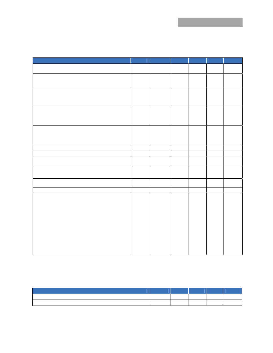
Electrical Specifications
(continued)
Parameter
Device
Symbol
Min
Typ
Max
Unit
Output Voltage Set-point
(V
IN
=V
IN,nom
, I
O
=I
O, max
, T
c
=25°C)
All
V
O, set
27.5 28 28.5 V
dc
Output Voltage Set-Point Total Tolerance
(Over all operating input voltage, resistive load, and temperature
conditions until end of life)
All V
O
27.0
29.0
V
dc
Output Regulation
Line (V
IN
=V
IN, min
to V
IN, max
) All
0.1 0.2 %V
o,set
Load (I
O
=I
O, min
to I
O, max
) All
0.1 0.2 %V
o,set
Temperature (T
c
= -40ºC to +100ºC)
All
0.02 %/°C
Output Ripple and Noise on nominal output
(V
IN
=V
IN, nom
and I
O
=I
O, min
to I
O, max
)
RMS (5Hz to 20MHz bandwidth)
All
45 55 mV
rms
Peak-to-Peak (5Hz to 20MHz bandwidth)
All
80
200
mV
pk-pk
External Capacitance
All,
except -T
C
O
440 6500
μF
Without the Tunable Loop
1
-T
C
O,
440 470
μF
With the Tunable Loop
2
-T C
O
440
10,000
μF
Output Power (V
o
=28V to 35.2V)
All
P
O,max
450 W
Output Current
All
I
o
0
16.0
A
dc
Output Current Limit Inception (Constant current until V
o
<
V
trimMIN
,
duration <4s)
All
I
O, lim
17.5
21.0 A
dc
Output Short Circuit Current (V
O
≤ 0.25V
dc
)
All
I
O, sc
60
A
pk
Hiccup mode
5
A
rms
Efficiency
V
IN
=V
IN, nom
, T
c
=25°C I
O
=I
O, max ,
V
O
= V
O,set
All
η 93.0
93.5
%
Switching Frequency
f
sw
175
kHz
Dynamic Load Response
(Io/t=1A/10s; V
in
=V
in
,nom; T
c
=25°C; Tested with a 470 μF
aluminum and a 10 µF ceramic capacitor across the load.)
Load Change from Io= 50% to 75% of Io,max: Peak Deviation
Settling Time (Vo<10% peak deviation)
All
V
pk
t
s
1
1.0
%V
O, set
ms
Load Change from Io= 25% to 50% of Io,max: Peak Deviation
Settling Time (Vo<10% peak deviation)
V
pk
t
s
1
1.0
%V
O, set
ms
(Io/t=2A/10s; V
in
=V
in
,nom; T
c
=25°C; Tested with a 880 μF
aluminum and a 10 µF ceramic capacitor across the load.)
Load Change from Io= 0% to 75% of Io,max: Peak Deviation
Settling Time (Vo<10% peak deviation)
All
V
pk
t
s
2
1.0
%V
O, set
ms
Load Change from Io= 75% to 0% of Io,max: Peak Deviation
Settling Time (Vo<10% peak deviation)
V
pk
t
s
2
1.0
%V
O, set
ms
1
Use a minimum 2 x 220uF output capacitor. Recommended capacitor is Nichicon PM series, 220uF/35V. If the ambient temperature at module
startup is between 0
O
C and -10
O
C, use a minimum 3 x 220uF capacitors, and between -10
O
C and -20
O
C, use a minimum 4 x 220uF capacitors. For
startup below -20
O
C, use 440uF minimum polymer capacitors.
2
External capacitors may require using the new Tunable Loop feature to ensure that the m
odule is stable as well as getting the best transient
response. See the Tunable Loop section for details.
Isolation Specifications
Parameter
Symbol
Min
Typ
Max
Unit
Isolation Capacitance
C
iso
15
nF
Isolation Resistance
R
iso
10
MΩ