Sstw00, 3a0a ba, Arracuda – GE Industrial Solutions SSTW003A0A Barracuda Series User Manual
Page 9: A™ series, S; dc-dc, C conver, Rter powe, Er modu, Data sh, Heet
G
S
3
c
a
3
C
P
P
d
d
E
F
c
F
F
F
p
L
T
u
c
m
c
m
p
GE
SSTW00
36-75Vdc In
March 26, 2013
current that ca
ambient tempe
3m/s (600 ft./m
Curves section.
Please refer to t
Process For Op
detailed discuss
device tempera
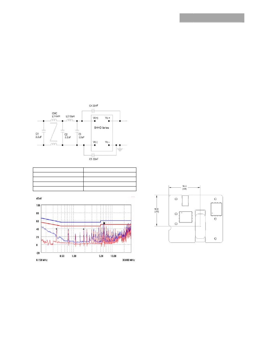
EMC Requir
Figure 16 show
conducted emis
Ref
C1 , C
C4
L
L
Figure 16. Sugg
Figure 17. EMC
For further info
please refer to t
Layout Con
The SSTW powe
used in fine pitc
component clea
module and the
copper areas o
module. Also a
power module.
3A0A Ba
nput; 5.0Vd
n be delivered
erature (T
A
) for n
min) are shown
the Application
en-Frame Boa
sion of therma
atures.
rements
ws a maximum
ssion limits of E
f Des
C2, C3
4, C5
L1
L2
gested Configu
C signature usi
rmation on des
the FLTR100V1
nsideration
er module serie
ch system card
arance betwee
e mounting bo
n the outer lay
void placing vi
arracuda
dc, 3A, 15W
©
by each modu
natural convec
in the respectiv
n Note “Therma
rd-Mounted Po
al aspects inclu
filter configura
EN55022 Class
2
3
4m
10
uration for EN
ing above filte
signing for EMC
10 data sheet (
ns
es are low prof
d architectures
en the bottom
ard is limited. A
yer directly und
a interconnect
a™ Series
W Output
©2012 General E
ule versus local
ction and up to
ve Characteris
al Characteriza
ower Modules”
ding maximum
ation to meet th
s B.
Filter
.2uF/100V
33nF Y cap
mH CM choke
uH inductor
55022 Class B
er.
C compliance,
FDS01-043EPS
file in order to b
s. As such,
of the power
Avoid placing
derneath the po
ts underneath
s; DC-DC
lectric Company
l
o
tics
ation
” for a
m
he
B.
S).
be
ower
the
For a
shee
The S
Thro
Thr
The
SAC
com
singl
RoHS
free
3C/
that
210
260
Hole
solde
proc
cons
Sur
Pick
The S
open
asse
The S
mag
Note
Figu
Z Pla
The ‘
nom
Noz
The
fram
whe
Varia
plac
proc
The
oper
C Conver
y. All rights reserv
additional layo
et.
SSTW family of
ough-Hole (TH)
ough-Hole S
RoHS-complia
(Sn/Ag/Cu) Pb-
ponents. They
le or dual wave
S-compliant fin
wave soldering
/s is suggested
the temperatu
C. For Pb sold
C, while the Pb
e module is also
ering. Refer to
cess details. If a
sult with your G
rface Moun
k and Place
SSTW-SR serie
n-frame constr
embly within a
SSTW-SR serie
gnetic compone
e: All dimension
re 18. Pick and
ane Height
‘Z’ plane heigh
minal with an RS
zzle Recomme
module weight
me construction
n compared w
ables such as n
ement speed s
cess.
minimum reco
ration is 5mm.
rter Powe
ved.
ut guide-lines,
f power modul
or Surface Mo
Soldering In
nt (Z codes) thr
-free solder an
y are designed
e soldering ma
nish that is com
g processes. A
. The wave pre
ure of the powe
er, the recomm
b-free solder po
o compatible w
the Reflow Sol
additional info
GE representat
nt Informat
s of DC-to-DC
ruction and are
fully automate
s modules are
ent surface to
ns in mm [in].
d Place Locatio
t of the pick an
SS tolerance of
endations
t has been kep
n. Even so, they
with convention
nozzle size, tip
should be cons
ommended noz
The maximum
Data Sh
er Modu
refer to the FL
es is available
unt (SMT) solde
nformation
rough-hole pro
d RoHS-compl
to be processe
achines. The pi
mpatible with b
maximum pre
eheat process
er module boa
mended pot tem
ot is 270C ma
with paste-in-h
dering Informa
rmation is nee
ive for more de
tion
power convert
e designed for
ed manufacturi
designed to us
allow for pick a
on.
nd place locatio
f +/-0.25 mm.
pt to a minimum
y have a relativ
nal SMT compo
style, vacuum
sidered to optim
zzle diameter fo
m nozzle outer d
heet
les
Page
LTR100V10 dat
for either
ering.
oducts use the
iant
ed through
ns have an
both Pb and Pb
eheat rate of
should be such
rd is kept below
mperature is
ax. The Throug
ole reflow
ation section fo
ded, please
etails.
ters use an
surface mount
ing process.
se the main
and place.
on is 7.50mm
m by using ope
vely large mas
nents.
pressure and
mize this
or reliable
diameter, whic
e 9
a
b-
h
w
h
or
t
en
ss
h