Data sheet, Surface mount information – GE Industrial Solutions ESTW015A0A Barracuda Series User Manual
Page 11
GE
Data Sheet
ESTW015A0A Barracuda™ Series; DC-DC Converter Power Modules
36-75Vdc Input; 5.0Vdc, 15A, 75W Output
March 28, 2013
©2012 General Electric Company. All rights reserved.
Page 11
Surface Mount Information
(continued)
Reflow Soldering Information
The surface mountable modules in the ESTW family use our
newest SMT technology called “Column Pin” (CP) connectors.
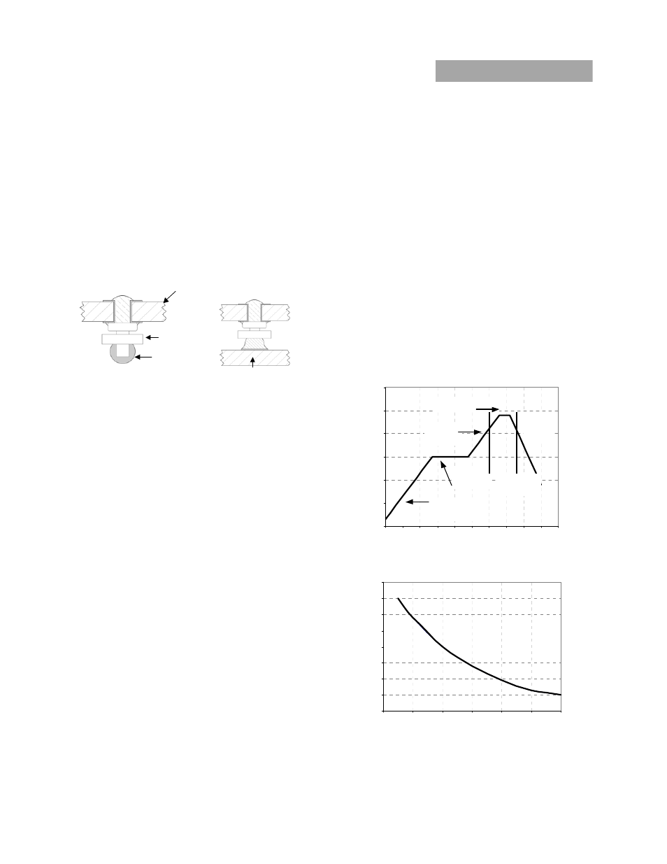
Figure 25 shows the new CP connector before and after
reflow
soldering onto the end-board assembly. The CP
is
constructed from a solid copper pin with an integral solder
ball attached, which is composed of tin/lead (Sn/Pb) solder
for non-Z codes, or Sn/Ag
3
/Cu (SAC) solder for –Z codes.
EHHD Board
Insulator
Solder Ball
End assembly PCB
Figure 21. Column Pin Connector Before and After Reflow
Soldering .
The CP connector design is able to compensate for large
amounts of co-planarity and still ensure a reliable SMT
solder joint. Typically, the eutectic solder melts at 183
o
C
(Sn/Pb solder) or 217-218
o
C (SAC solder), wets the land, and
subsequently wicks the device connection. Sufficient time
must be allowed to fuse the plating on the connection to
ensure a reliable solder joint. There are several types of SMT
reflow technologies currently used in the industry. These
surface mount power modules can be reliably soldered
using natural forced convection, IR (radiant infrared), or a
combination of convection/IR. The following instructions
must be observed when SMT soldering these units. Failure to
observe these instructions may result in the failure of or
cause damage to the modules, and can adversely affect
long-term reliability.
Tin Lead Soldering
The ESTW015A0A power modules are lead free modules and
can be soldered either in a lead-free solder process or in a
conventional Tin/Lead (Sn/Pb) process. It is recommended
that the customer review data sheets in order to customize
the solder reflow profile for each application board
assembly. The following instructions must be observed
when soldering these units. Failure to observe these
instructions may result in the failure of or cause damage to
the modules, and can adversely affect long-term reliability.
In a conventional Tin/Lead (Sn/Pb) solder process peak
reflow temperatures are limited to less than 235
o
C.
Typically, the eutectic solder melts at 183
o
C, wets the land,
and subsequently wicks the device connection. Sufficient
time must be allowed to fuse the plating on the connection
to ensure a reliable
solder joint. There are several types of SMT reflow
technologies currently used in the industry. These surface
mount power modules can be reliably
soldered using
natural forced convection, IR (radiant infrared), or a
combination of convection/IR. For reliable soldering the
solder reflow profile should be established by accurately
measuring the modules CP connector temperatures.
Lead Free Soldering
The –Z version of the ESTW015A0A modules are lead-free
(Pb-free) and RoHS compliant and are both
forward and backward compatible in a Pb-free and a SnPb
soldering process. Failure to observe the instructions below
may result in the failure of or cause damage to the modules
and can adversely affect long-term reliability.
RE
FLOW T
EMP
(
C)
REFLOW TIME (S)
Figure 22. Reflow Profile for Tin/Lead (Sn/Pb) process.
MAX T
EMP
SO
LDE
R (
C)
Figure 23. Time Limit Curve Above 205
o
C for Tin/Lead
(Sn/Pb) process
0
50
100
150
200
250
300
P reheat zo ne
max 4
o
Cs
-1
Soak zone
30-240s
Heat zo ne
max 4
o
Cs
-1
P eak Temp 235
o
C
Co oling
zone
1-4
o
Cs
-1
T
lim
above
205
o
C
200
205
210
215
220
225
230
235
240
0
10
20
30
40
50
60