GE Industrial Solutions A Series Lighting Control Panelboards Replacement of Back plane User Manual
A series, Lighting control panel boards
Removal of Existing Back Plane Assembly:
1. Ensure that the Installer is properly grounded while
working near the controller box area
2. Remove the front cover and dead front of the Panel board
/ Integrated switch board
3. Remove the center barrier by unscrewing the four mtg
screws which covers the line straps of each breaker.
4. Remove all the breakers on the side of back plane that
needs to be replaced
4a) Unscrew the breaker line strap mtg screw
4b) Hold the breaker and lift upwards & avoid it rotating
5. Unscrew the connecting cables ends to DB25 connector
on the back plane assembly to be replaced.
6. Remove all the caplugs on the back plane assembly to be
replaced. Save caplugs for new back plane assembly.
7. Unscrew the hold down bracket mtg screw as per side
required on the controller box and then remove the hold
down bracket.
8. Unscrew Philips head screws holding the tray cover &
save them.
9. Remove the tray cover by lifting it.
10. Remove the back plane assembly.
Reinstallation instructions:
1. Locate the back plane assembly into the embossment
provided in panel plastic mounting base tray and
embossment provided on the top & bottom end caps.
2. Drop down the tray cover so as it snaps on all the plastic
tray snap tabs
3. Tighten all the Philips headed screws to torque of 10 lb-
inch to the tray cover so as to secure the back plane
firmly.
4. Assemble the hold down bracket and fastened it to the
controller box with hold down mtg screw & torque to 10 lb-
inch
5. Insert the caplug on the DB25 Pin connector of back plane
assembly on the other end.
6. Connect the DB25 connector cables by pressing the end
of the cables firmly and tighten two knurled screws of
cable end to torque of 5-10 lb-inch.
7. Install the breakers on the side on the replaced back plane
assembly. Breakers to be mounted straight down
7a) Align breaker line strap screw to bus bar strap mtg
hole and breaker connector to back plane connector.
7b) Push the breaker on to the plastic base mtg rail.
7c) Torque the line strap screw to 35 lb-inch.
8. Install the center barrier and tighten mtg the screws to hold
it firmly. Press this barrier on each breaker so it covers the
Line straps properly.
9. Install the dead front and front cover of the Panel board /
Integrated Switch board.
A Series
®
Lighting Control Panel boards
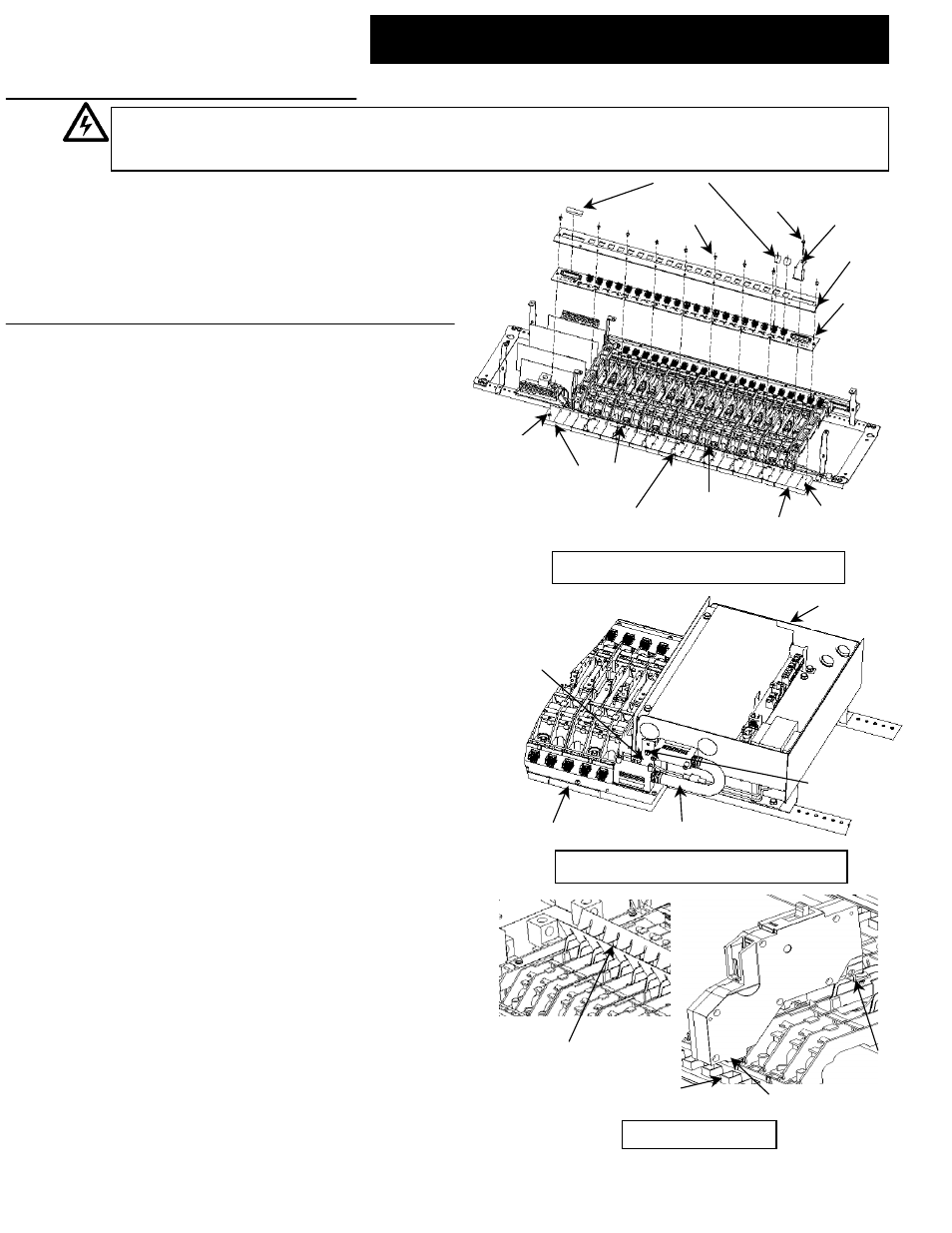
Externally Mounted Controller Assembly
Controller
Box
DB25 Connector Cable
Back Plane Assy
Hold down
bracket mtg screw
Hold down
Bracket
Snap
tab
Top
End Cap
Top end cap
Embossment
Plastic Base tray
Embossment
Bottom end cap
Embossment
Bottom
End Cap
Panel mtg
Base
Caplugs
Tray cover
Back Plane:
ASRGLCPCB12
ASRGLCPCB18
ASRGLCPCB24
ASRGLCPCB30
ASRGLCPCB36
ASRGLCPCB42
Philips head
screws
Hold down bracket
mtg screw
Hold down
Bracket
Replacement of Back plane assembly
Catalog No.
Qty
Description
ASRGLCPCB12
1
12 Ckt Back Plane replacement kit
ASRGLCPCB18
1
18 Ckt Back Plane replacement kit
ASRGLCPCB24
1
24 Ckt Back Plane replacement kit
ASRGLCPCB30
1
30 Ckt Back Plane replacement kit
ASRGLCPCB36
1
36 Ckt Back Plane replacement kit
ASRGLCPCB42
1
42 Ckt Back Plane replacement kit
WARNING: Danger of electrical shock or injury. Turn OFF power service to the line side of the panel board
or switchboard before working inside the equipment or removing any component. Equipment is to be
installed and maintained by properly trained and qualified personnel only.
Internally Mounted Controller Assembly
DEH41093 Installation Instructions R02
g
Line
Strap
Back Plane
Connector
Breaker connector
Breaker Installation
Center Barrier
GE Consumer & Industrial General Electric Company, Plainville, CT 06062
2004 General Electric Company
DEH41093 R02