Geh-5643p2, Attention – procedure for aluminum terminations – GE Industrial Solutions Spectra Series Power Panelboards AMC6QD and AMC4QD User Manual
Page 2
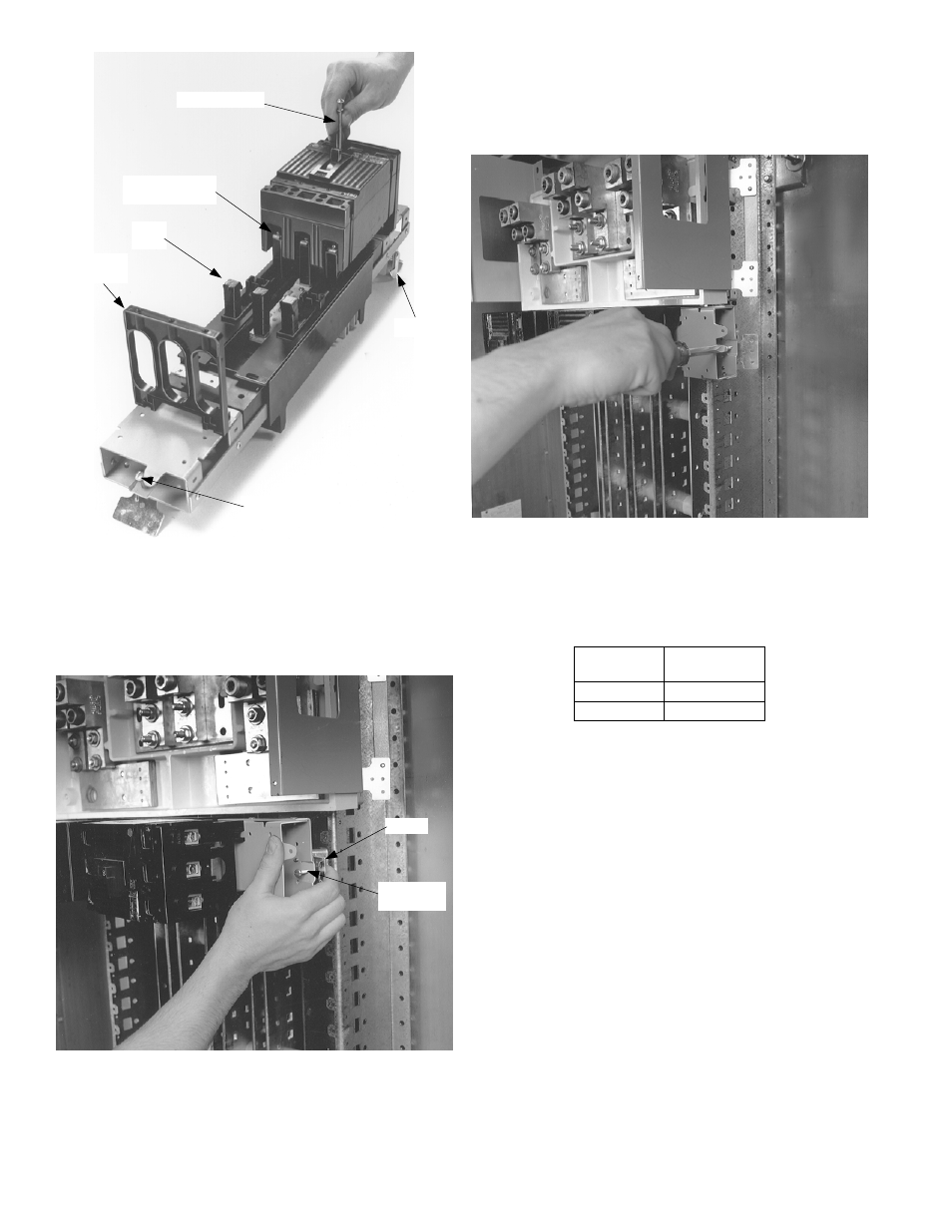
Figure 4. Installing the breaker on the module.
4. Position the module.
Loosen the latch lock screws and
fully retract the latches. Line up the guide fingers on
both ends of the module with the notches in the
panelboard interior rails, as shown in Figure 5. Allow
no space between units.
Figure 5. Positioning the breaker module.
5. Install the module.
Latch one side of the circuit
breaker module. Release the rail latch. Pivot the
module onto the bus bars and engage the second
latch. Release the rail latch. Tighten the rail latch
screws to 25 in.-lbs, as shown in Figure 6.
Figure 6. Installing the breaker module.
6. Wire the circuits.
Refer to the label on the circuit
breaker for the proper tightening torque. levels
7. Filler plate kits.
Install filler plate kits, as listed in
Table 1.
Filler Plate
Cat. No.
Module Type
AFP3QDD
AMC6QD
AFP2QDD
AMC4QD
Table 1. Filler plate kit for each breaker module type.
Attention – Procedure for Aluminum
Terminations
1.
Strip the insulation, being careful to not nick the wire.
2.
Clean the wire strands with a wire brush.
3.
Thoroughly coat the stripped conductor with a
suitable antioxidant compound, such as ALNOX or
PENETROX A13.
4.
Insert the conductor and tighten the connector screw
to the torque indicated on the rating label.
Stud
Post
1
/
4
-20 Screw &
Conical Washer
#10-32 Screw
Filler
Support
Latch Lock
Screw
Latch
Latch Lock
Screw
Latch