Installing the trip unit – GE Industrial Solutions ProTrip Conversion Kits LA-600, LA-800, and LA-1600 User Manual
Page 9
9
Installing the Trip Unit
1. On LA-600 and LA-800 installations, remove the
microswitch adjusting bolt on the trip unit
mounting plate.
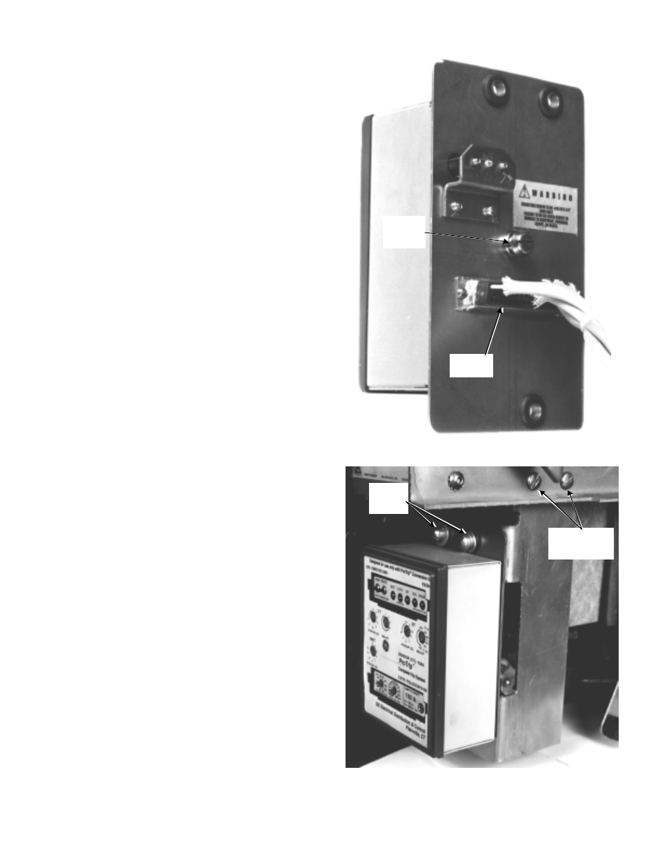
2. Remove and the trip unit mounting screw from
the rear of the trip unit. Place the trip unit in
position on the mounting plate, with the 50-pin
connector aligned with the opening in the plate.
Secure with the previously removed trip unit
mounting screw, as shown in Figure 8.
3. Insert the 50-pin female connector on the wiring
harness into the trip unit connector through the
rear of the mounting plate. Secure to the mount-
ing plate with the two #4-40 screws and lock
washers provided, as shown in Figure 8.
4. Place the trip unit and mounting plate in posi-
tion on the support bracket. Secure with three
1
/
4
-20 screws, lock washers, and flat washers
into the tapped holes in the support bracket, as
shown in Figure 9.
5. Place the two slotted mounting holes in the
support bracket behind the two existing holes in
the breaker frame, as shown in Figure 9. Secure
with the
1
/
4
-20 screws, flat washers, lock
washers, and nuts provided.
6. Pass the current sensor and flux shifter leads
from the front to the rear through the hole on
the lower left side (viewed from the rear) of the
breaker frame.
7. If a neutral sensor is to be used in the equip-
ment, pass the corresponding connector
through the rear-frame hole with the CT leads.
Otherwise, tie it to some convenient point on
the breaker frame with wire ties.
8. On LA-1600 installations, adjust the microswitch
adjusting bolt so that the microswitch is off
when the breaker is open and on when the
breaker is closed.
Figure 8. Attaching the trip unit to the mounting plate.
Figure 9. Trip unit mounted on the breaker (LA-600 shown).
Trip Unit
Mounting
Screw
50-Pin
Connector
Support Bracket
Mounting
Screws
Mounting
Plate
Screws