GE Industrial Solutions Spectra Series Power Panelboards AMC6EY and AMC6QB User Manual
Spectra series™ power panelboards, General, Installation
g
Spectra Series™ Power Panelboards
Circuit Breakers and Modules
WARNING:
Danger of electrical shock or injury.
Turn
OFF power ahead of the panelboard or
switchboard before working inside the
equipment or removing any component
.
Do
not remove circuit protective devices or any
other component until the power is turned
OFF.
General
These instructions apply to the following catalog numbers:
•Circuit breaker modules AMC6EY and AMC6QB
•Circuit breaker frames TEY, THQB, and THHQB
Installation
1. Prepare the module.
Attach the filler supports to each
end of the module using the #10-32
x
3
/
4
"
hex-head
screws, as shown in Figure 1. Tighten the screws to
15–20 in.-lbs. Loosen the latch-locking screws.
2. Install the circuit breaker(s).
Hook the load end of the
circuit breaker onto the module and secure with the
captive screws on the line end, as shown in Figure 1.
Tighten the screws to 25 in.-lbs.
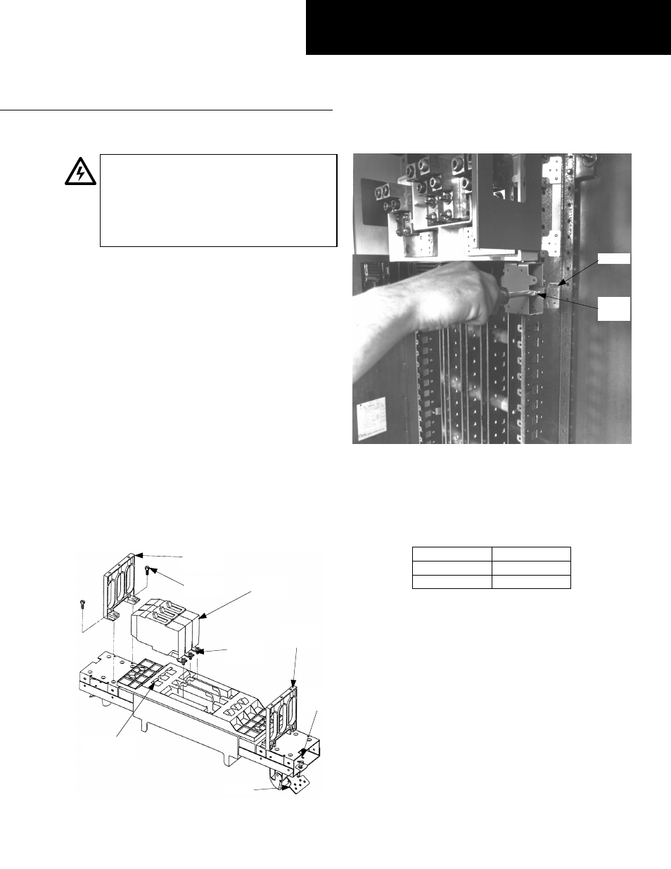
3. Install the module.
Fully retract the latches on the end
of the module, shown in Figure 1, and hook one side
of the module on the interior rail. Release the latch.
Pivot the module onto the bussing and engage the
second latch. Release the latch. Tighten the latch
screws to 25 in.-lbs., as shown in Figure 2.
Figure 1. Installing the circuit breaker on the module.
Figure 2. Attaching the circuit breaker module to the panelboard
interior.
4. Wire the circuits.
Refer to the rating label on the
circuit breaker for the proper tightening torques.
5. Filler plate kits.
Install the appropriate filler plate kit
as listed in Table 1.
Breaker Module
Filler Plate Kit
AMC6EY
AFP3EYD
AMC6QB
AFP3QBD
Table 1. Filler plate kit for each breaker module type.
Attention – Procedure for Aluminum
Terminations
1.
Strip the insulation, being careful to not nick the wire.
2.
Clean the wire strands with a wire brush.
3.
Thoroughly coat the stripped conductor with a
suitable antioxidant compound, such as ALNOX or
PENETROX A13.
4.
Insert the conductor and tighten the connector screw
to the torque indicated on the rating label.
GEH5677 Installation Instructions
R03
Circuit
Breaker
Filler
Support
#10-32
Screw
Filler
Support
Load-End
Connection
Captive
Screws
Latch
Latch
Screw
Latch
Screw
Latch