GE Industrial Solutions Spectra Series ACT Transient-Voltage User Manual
Application, Installation, Act transient-voltage surge suppressors
g
Spectra Series™ Power Panelboards &
Switchboard Panels
ACT Transient-Voltage Surge Suppressors
Application
These kits are provided for installation of ACT Transient-
Voltage Surge Suppressor (TVSS) in Spectra bolt-on and
plug-in panels and switchboards. The catalog numbers
and descriptions of the available units are listed in Table
1. The K suffix denotes field-installable kits.
All TVSS units are 7X (9
5
/
8
") high and the minimum
equipment width is a 27-inch wide Spectra panelboard or
35-inch wide Spectra switchboard.
Catalog Number
System
Voltage, Vac Configuration
Surge
Current per
Mode, kA
ATME120S065K
120/240
1Ø
65
ATME120S800K
120/240
1Ø
80
ATHE120S100K
120/240
1Ø
100
ATHE120S150K
120/240
1Ø
150
ATHE120S200K
120/240
1Ø
200
ATME120Y065K
208Y/120
3Ø, 4W
65
ATME120Y800K
208Y/120
3Ø, 4W
80
ATHE120Y100K
208Y/120
3Ø, 4W
100
ATHE120Y150K
208Y/120
3Ø, 4W
150
ATHE120Y200K
208Y/120
3Ø, 4W
200
ATME240D065K
240 ∆
3Ø, 3W
65
ATME240D080K
240 ∆
3Ø, 3W
80
ATHE240D100K
240 ∆
3Ø, 3W
100
ATHE240D150K
240 ∆
3Ø, 3W
150
ATHE240D200K
240 ∆
3Ø, 3W
200
ATME277Y065K
480Y/277
3Ø, 4W
65
ATME277Y080K
480Y/277
3Ø, 4W
80
ATHE277Y100K
480Y/277
3Ø, 4W
100
ATHE277Y150K
480Y/277
3Ø, 4W
150
ATHE277Y150K
480Y/277
3Ø, 4W
200
ATME480D065K
480 ∆
3Ø, 3W
65
ATME480D080K
480 ∆
3Ø, 3W
80
ATHE480D100K
480 ∆
3Ø, 3W
100
ATHE480D150K
480 ∆
3Ø, 3W
150
ATHE480D200K
480 ∆
3Ø, 3W
200
ATME240H065K
240/120 ∆
3Ø, 4W
65
ATME240H080K
240/120 ∆
3Ø, 4W
80
ATHE240H100K
240/120 ∆
3Ø, 4W
100
ATHE240H150K
240/120 ∆
3Ø, 4W
150
ATHE240H200K
240/120 ∆
3Ø, 4W
200
Table 1. Catalog numbers and specifications for ACT transient-
voltage surge suppressor kits.
Installation
WARNING:
Danger of electrical shock or injury.
Turn
OFF power ahead of the panelboard or
switchboard before working inside the
equipment or removing any component
.
Equipment is to be installed and maintained by
properly trained and qualified personnel only.
The numbers in brackets in the text and figures refer to
the items in Tables 2 and 3.
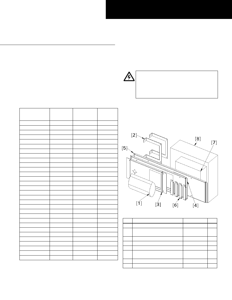
1. Confirm the contents of the kit.
Figure 1 illustrates the
contents of the kit, with the parts listed in Table 2.
Figure 2 illustrates the hardware included in the kit
([1] in Table 2), with the parts listed in Table 3.
Figure 1. Typical TVSS kit contents.
Item Description
Part #
Qty.
1
TVSS kit hardware
10082305G3
1
2
Cover support for 36W, 40W,
44W, and 45W
10083033P2
2
3
Cover for 27W, 31W and 35W
10087203G1
1
4
Cover for 36W and 40W
10087203G2
1
5
Cover for 44W and 45W
10087203G3
1
6
Cover support for 27W, 31W
and 35W
252B1477P4
4
7
Neutral and ground wire kit
ATHMEGNDN
1
8
TVSS in package
TVSS_UNIT
1
Table 2. Parts list for the TVSS kit.
DEH40443 Installation Instructions
R02