GE Industrial Solutions Spectra Series Power Panelboards Permanent Circuit Markers User Manual
GE Industrial Solutions Equipment
g
Spectra Series™ Power Panelboards
Permanent Circuit Markers
WARNING:
Danger of electrical shock or injury.
Turn
OFF power ahead of the panelboard or
switchboard before working inside the
equipment or removing any component
.
Equipment is to be installed and maintained by
properly trained and qualified personnel only.
These instructions apply to installation of catalog
numbers APN49 (for numbers 1–49) and APN99 (for
numbers 1–99). Table 1 lists the contents of the marker
kits. Table 2 lists the marker strips used for various interior
heights.
Cat. No.
Description
Qty.
252B1679P1
Marker strip (5X), 10 circuits
2
252B1679P2
Marker strip (10X), 20 circuits
2
252B1679P3
Marker strip (13X), 26 circuits
2
N605P13005B Thread-forming screw, #6-32 x
5
/
16
24
264V287P1–49
264V287P1–99
Permanent marker tabs (in APN49)
Permanent marker tabs (in APN99
49
99
Table 1. Contents of the permanent circuit marker kits.
Interior Height,
X = 1
3
/
8
"
Marker Strips,
Two Each
13
252B1679P3
18
252B1679P1
252B1679P3
23
252B1679P2
252B1679P3
28
252B1679P1
252B1679P2
252B1679P3
33
252B1679P2
252B1679P3
38
252B1679P1
252B1679P2
252B1679P3
43
252B1679P2
252B1679P3
48
252B1679P1
252B1679P2
252B1679P3
53
252B1679P2
252B1679P3
Table 2. Marker strips to use for various interior heights.
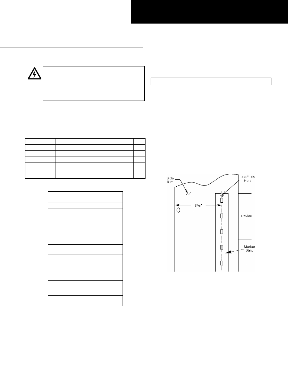
Drill the Mounting Holes
WARNING:
Eye protection is required for this operation.
Use a marker as a template. Place the strip at the
dimension shown in Figure 1 (from the outside edge of
the side trim) and directly opposite the mounted devices.
Drill a 0.120-inch diameter hole (#31 drill) at each end of
the marker. Some markers will have more than two holes,
depending on their lengths.
Install the Marker Strips
Insert a marker into the retainer strips mounting holes
next to the circuit to be identified. Form the marker legs
over to secure the marker in the mounting strip hole.
When all the required circuit markers are attached, install
the retainer strip to the front shield with the #6-32 pan-
head thread-forming screws provided, as shown in Figure
2.
Figure 1. Drilling the mounting holes.
GEH5598 Installation Instructions
R02