GE Industrial Solutions Tranquell Series Low and Medium User Manual
Page 14
2020005003 (12/09) Page 14 of 18
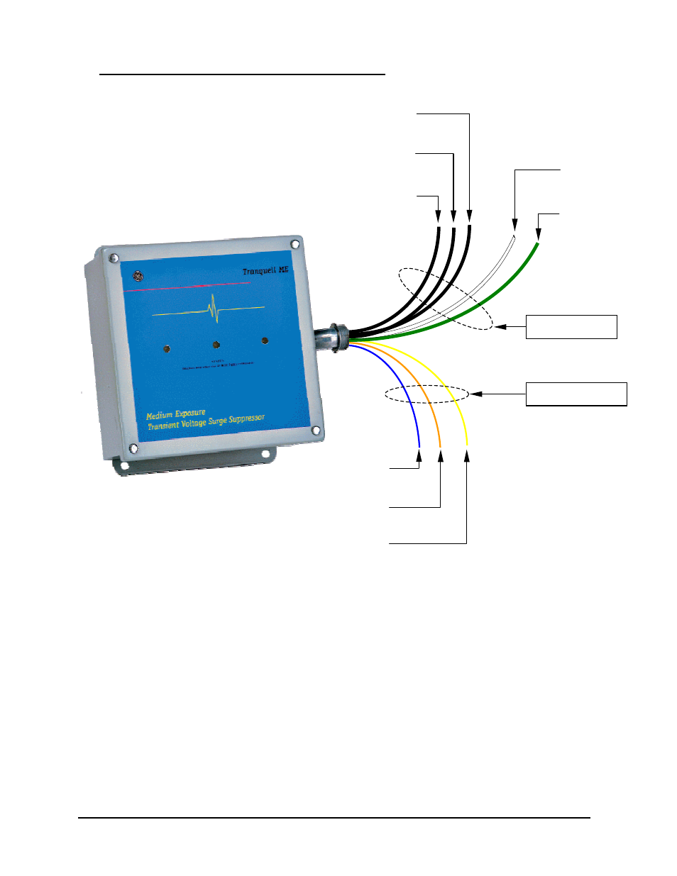
POWER WIRING AND REMOTE ALARM LOCATIONS
The above illustration represents the wiring and alarm contacts for both the TLE and TME Wall Mounted SPD
for 3 phase applications. (Split/Single phase versions will have only 2 black power wires for connection.)
Black Wires are marked and identified as Phase A, Phase B, Phase C.
Various mounting orientations are possible and will not affect the performance of the SPD if wire connections
and cable length are kept to a minimum.
Notice For High Leg Delta Power Systems:
SPD model types that are intended for High Leg Delta applications are configured and marked with
Phase B as the intended High Leg connection point. Attempting to connect the SPD Phase C or
Phase A conductor to the system High Leg will result in immediate SPD failure.
Labeled “Phase A”
(Black)
Labeled “Phase B”
(Black)
Labeled “Phase C”
(Black)
Ground
(Green)
Neutral
(White)
Power Wiring
Alarm Contacts
COM
(Yellow)
NC
(Blue)
NO
(Orange)
Remote Contact Status
Modes
Normal Indication:
NO – COM = Closed
NC – COM = Open
Alarm Indication:
NO – COM = Open
NC – COM = Closed