GE Industrial Solutions EntelliGuard G Undervoltage Release User Manual
Entelliguard, G circuit breaker, Accessories
Introduction
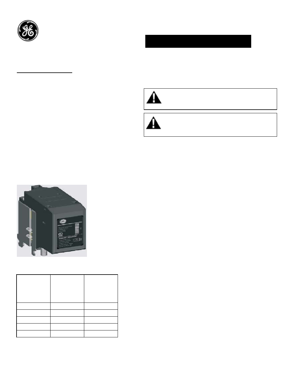
Undervoltage Release:
A device designed to open the breaker contacts
and to prevent the breaker from closing when in
a ‘No volt’ condition. On a de-energization the
Undervoltage release activates the circuit breaker
mechanism and ensures a rapid disconnection of
the main contacts and the device prevents the
Power Circuit Breaker from closing. The
EntelliGuard G™ Undervoltage release is
designed to react within a pre-defined Voltage
band, only reacting when the voltage supply
drops below the limits of this band. To prevent
nuisance tripping due to short power
interruptions or ‘Brown Outs’ the device has a
built in delay of 50 Milliseconds when Voltage is at
or below 50% of rated Voltage. Two under
voltage Releases can be mounted in each Power
Circuit Breaker.
Table 1.
Catalog No DC Voltage AC Voltage
GUVT024DR
24V
GUVT030DR
30V
GUVT048R
48V
48V
GUVT060DR
60-72V
GUVT120R
110-130V
120-130V
GUVT208AR
208V
GUVT240R
220-240V
220-240V
GUVT277R
250V
250-277V
DEH-41410 Installation Instructions
EntelliGuard
®
G Circuit Breaker
Accessories
Undervoltage Release
WARNING: Before installing any accessories, turn the
breaker OFF, disconnect it from all voltage sources,
and discharge the closing spings.
For an External Time Delay Module (1-3 second
delay) refer to Pub DEH-41406
Inrush Power: 350VA
Steady state : 40VA
Use the following procedure to install the
Undervoltage Device accessory into the circuit
breaker.
1. Verify that the rating on the Undervoltage
Device identification plate matches the voltage
rating required for the application, as listed in
Table 1.
2. Turn the breaker off and discharge the closing
springs by depressing the OFF and ON buttons in
the sequence OFF-ON-OFF. Verify that the
breaker OFF-ON indicator shows OFF on a green
background and that the charge indicator shows
DISCHARGE on a white background. If installing
in a draw-out type breaker remove breaker from
adaptor (cassette) before continuing.
AVERTISSEMENT: Avant d’installer tout accessoire,
mettre le disjoncteur en position OFF, le déconnecter
de toute tension d’alimentation , et décharger les
resorts d’armement
3. Loosen the 6 screws on front cover (fascia)
using a posidrive screw driver as shown in Fig 1.B
Rotate the charging handle down and slide the
front cover over the handle to remove the front
cover as shown in Fig. 1.C.
1